 Aller au contenu
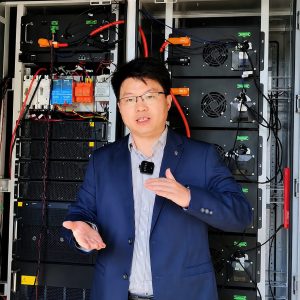
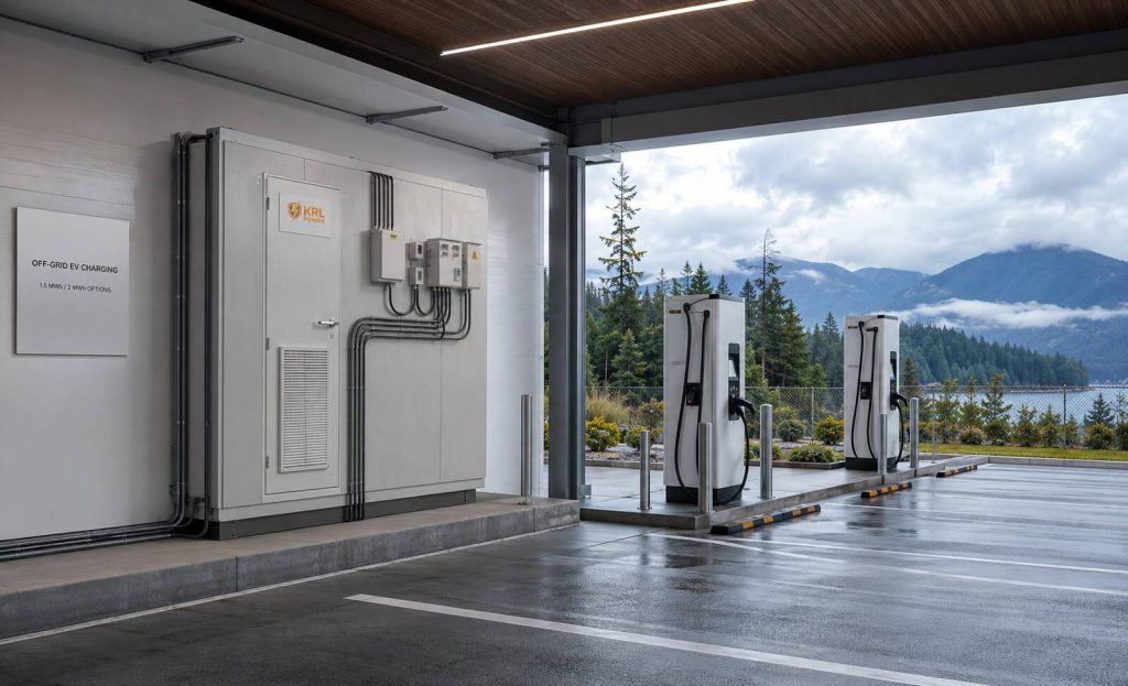
KRL Power can structure the British Columbia project around a single-phase diesel source, a three-phase EV charger bus, indoor equipment space and two published BESS classes: 1,5 MWh / 750 kW ou 2 MWh / 1 MW. The quotation needs named boundaries for the BESS, PCS, transformer, protection and controls.
The commercial package starts with an approved single-line diagram, charger-duty schedule, generator data sheet, preliminary indoor layout and final-BOM evidence register. KRL’s public B2M6L 1.5 MWh and 2 MWh energy-storage configurations list 400/230 Vac three-phase AC, a diesel-generator port, liquid cooling and a fire-protection system.
Match the Customer Requirement to a Published KRL Product Class
KRL publicly lists 1,5 MWh / 750 kW et 2 MWh / 1 MW B2M6L configurations. The final selection follows the charger-duty profile, generator recharge window, usable state-of-charge range and auxiliary consumption.
| Customer decision | Publié sur la base KRL | Project selection action |
|---|---|---|
| Capacity range under review: 1 MWh or 2 MWh | B2M6L public table: 1.5 MWh or 2 MWh nominal energy | Compare the charging-duty profile with the 1.5 MWh and 2 MWh energy classes; define usable AC energy in the final offer |
| High-power EV charger output | 750 kW grid/off-grid AC for 1.5 MWh; 1 MW grid/off-grid AC for 2 MWh | Set the BESS power limit against the aggregate charger demand and the agreed charging diversity |
| Three-phase charger bus | 400/230 V CA, L1/L2/L3/N/PE, 50/60 Hz | Confirm charger input voltage, frequency, neutral arrangement, breaker frame and feeder schedule |
| Diesel source | Diesel-generator port: Yes | Show the generator phase, voltage, charging path and operating sequence on the approved single-line diagram |
| Indoor installation | 6,058 × 2,438 × 2,896 mm; approximately 15,000 kg or 19,500 kg | Approve the indoor route, floor loading, clearances, lifting plan, ventilation and fire design |
| BC certification request | Not stated publicly for the exact offered B2M6L configuration | Attach model-specific certificates and the local applicability statement to the final equipment list |
- 1.5 MWh / 750 kW: the first published container option above the initial 1 MWh planning target.
- 2 MWh / 1 MW: the published higher-capacity option for longer charging duty, energy reserve or future demand.
- AC-delivered energy: state separately from nominal battery energy and charge-session energy.
- Named equipment: record BESS model, PCS configuration, transformer, charger manufacturer and control interface in the commercial offer.
Define the Single-Phase Diesel and Three-Phase Charger Architecture
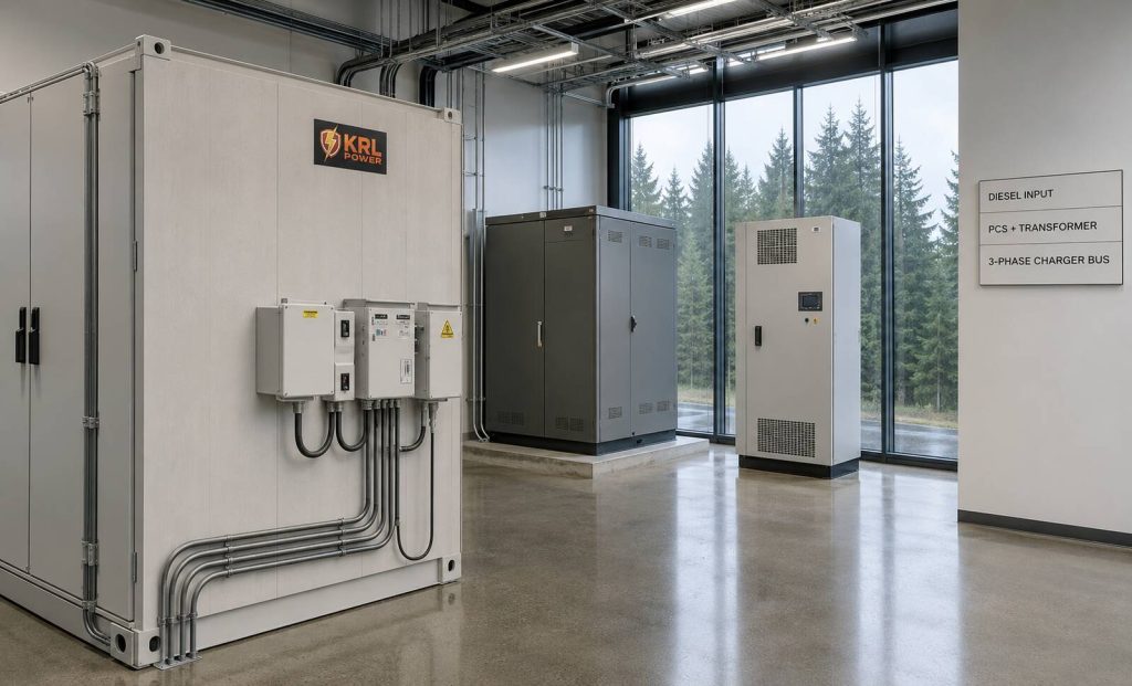
The central engineering decision is the connection between the customer’s single-phase diesel source and the required three-phase fast-charger bus. Price every electrical layer against the final phase, voltage, power and protection responsibility.
Confirm the Generator Input Boundary
The public B2M6L specification lists a diesel-generator port. Single-phase generator acceptance is Not stated publicly. The approved single-line diagram must name the phase-conversion or charging equipment that supplies the three-phase EV charger bus.
| Electrical layer | Required responsibility | Quotation evidence |
|---|---|---|
| Single-phase diesel generator | State rated kW/kVA, voltage, frequency, source impedance, fuel autonomy and generator controller | Generator datasheet, alternator data and approved operating sequence |
| Generator-to-storage charging path | Define phase conversion or charging equipment, current limit, synchronization requirements and control priority | Single-line diagram, converter/charger model and protection schedule |
| KRL BESS and PCS layer | Supply the agreed three-phase bus duty, energy reserve, communication and source-control function | KRL model datasheet, PCS configuration, BMS/EMS protocol and operating-mode schedule |
| Transformer | Match charger-bus voltage, vector group, earthing arrangement, impedance, losses and indoor thermal conditions | Transformer datasheet, connection drawing and separate price line |
| DC fast chargers | State each charger’s AC input, maximum demand, power-sharing logic and start sequence | Charger datasheets, charging-load profile and feeder schedule |
KRL’s BMS and PCS integration information supports the controls discussion. The final interface schedule must name the equipment accepting the single-phase generator source and the equipment forming the three-phase charger bus.
- Generator: state the charge limit and the permitted operating range.
- Charger bus: state the EV charger discharge limit and curtailment sequence.
- Transformer: name the party responsible for vector group, neutral point and earthing method.
- Protection : include reverse-power prevention, fault-current contribution and coordination settings.
- Acceptance: test generator start, BESS transition, charger energization, charger load step and controlled shutdown.
Choose 1.5 MWh or 2 MWh From the Charging-Duty Profile
The charging-duty profile sets the capacity decision. It records charger demand, simultaneous sessions, duration, minimum reserve, generator operating window and future expansion. The proposal should state AC-delivered energy at the charger bus, starting state of charge, ending state of charge and calculation condition.
| Illustrative charger-bus duty | AC energy delivered in one hour | Selection use |
|---|---|---|
| 250 kW aggregate charging demand | 250 kWh | Establishes a low-demand operating interval |
| 500 kW aggregate charging demand | 500 kWh | Tests simultaneous charging and generator recharge timing |
| 750 kW aggregate charging demand | 750 kWh | Aligns with the published 1.5 MWh configuration’s 750 kW AC power class |
| 1 MW aggregate charging demand | 1 000 kWh | Aligns with the published 2 MWh configuration’s 1 MW AC power class |
The table shows illustrative AC energy at the charger bus for one hour. The final capacity calculation includes PCS efficiency, transformer losses, charger efficiency, auxiliary demand, state-of-charge window, ambient condition, degradation reserve and contractual end point. KRL commercial energy storage selection guidance can support the input schedule.
- For every charger, log the rated power, expected average power, session duration and daily sessions.
- For the diesel source, state the available kW, permitted loading range and recharge period reserved for the BESS.
- For the BESS, state nominal energy, usable energy at the AC bus, continuous power and energy held for system recovery.
- For future expansion, state whether capacity, charger count or charger power changes first and reserve the required switchgear positions.
Compare LiFePO4 and Solid-State Quotations With Model-Level Evidence
The buyer requested LiFePO4 et à semi-conducteurs alternatives. KRL’s published B2M6L configurations use LiFePO4. For a solid-state or quasi-solid option, the exact commercial C&I model, certification, lifetime, usable energy and availability for this BC project are Not stated publicly.
| Quotation review point | LiFePO4 base offer | Solid-state or quasi-solid alternative |
|---|---|---|
| Named product basis | KRL B2M6L published 1.5 MWh or 2 MWh configuration | Exact model and configuration required |
| Published chemistry evidence | LiFePO4 | Technology-category reference; project model details require confirmation |
| Power and usable AC energy | 750 kW/1.5 MWh or 1 MW/2 MWh nominal configuration; usable AC energy requires the final calculation | Nameplate values, test conditions and usable AC energy required |
| BC-local documentation | Model-specific certificate package required | Model-specific certificate package required |
| Commercial comparison | BESS, PCS, transformer, installation, commissioning and warranty scope separated | Same scope boundary for a like-for-like comparison |
Use the same charger duty, generator duty, indoor layout, warranty boundary and acceptance test for both chemistry options. KRL solid-state battery technology category supports preliminary technology review. The purchase order requires a named final model, applicable certificate records and an approved performance boundary.
Price PCS, Transformer and EV-Charger Cable Boundaries Separately
The customer requested separate PCS et transformer pricing. The BESS-to-EV-charger cable sits outside the storage supply scope. Keep each boundary on a separate quotation line so the EPC can assign controls, protection and warranty responsibility.
| Commercial line item | Required scope statement | Decision owner |
|---|---|---|
| KRL BESS package | Model, nominal energy, AC power, installed PCS configuration, controls interfaces, cooling and fire system | KRL Power and the selected system integrator |
| Transformer | Voltage ratio, vector group, impedance, earthing, indoor thermal design, enclosure and test requirements | Transformer supplier and EPC electrical designer |
| EV-charger feeder cable | Excluded supply item; route, conductor, insulation, termination, containment and testing stated separately | EPC and charger installation contractor |
| Protection and controls | Relay application, metering, generator control, charger curtailment, emergency stop and communications | EPC controls lead with equipment suppliers |
| Commissioning and warranty | FAT/SAT, functional tests, response route, exclusions and owner responsibilities | All delivery parties named in one matrix |
KRL commercial and industrial energy storage solutions gives the product context. KRL OEM and ODM system-matching capability supports the integration discussion. The signed scope matrix controls final delivery.
Build the Indoor BC Evidence and Acceptance Package
Indoor installation requires a coordinated facility package. The published B2M6L dimensions and mass require an approved delivery path, floor-load review, service clearance, lifting plan, ventilation, fire-system integration, emergency isolation and access control.
Confirm BC Evidence Before Award
KRL publicly lists battery IP65, liquid cooling and a fire-protection system for the B2M6L product class. BC certification status for the final offered configuration is Not stated publicly. Attach model-specific certificates, applicability statements and approval-path evidence to the final BOM.
- Electrical: single-line diagram with generator, charging path, BESS, PCS, transformer, EV chargers, earthing and isolation.
- Equipment: final BOM with BESS model, PCS configuration, transformer, charger model, switchgear and communications.
- Compliance: model-specific data sheets, certificates, applicability statement and test reports.
- Indoor works: delivery route, floor loading, clearances, cable route, cooling path and emergency access.
- Acceptance: FAT/SAT covering generator start, storage charge, three-phase charger operation, load step, emergency stop and restoration.
- Warranty: responsible party, reporting path, service boundary and retained evidence.
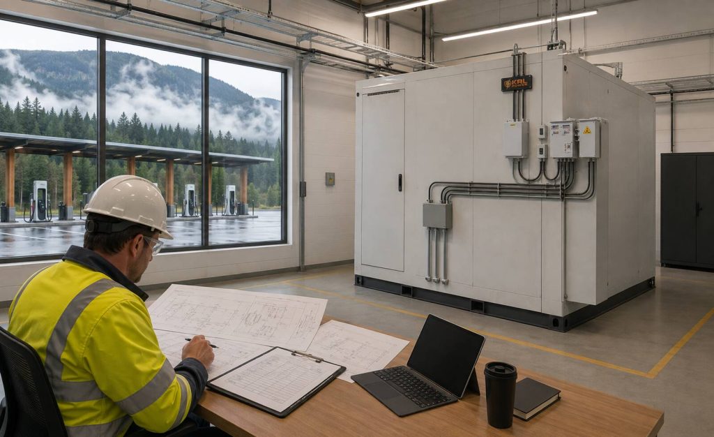
KRL testing and certification information et KRL packaging and transport information identify the product records to request. The BC package needs documents applicable to the exact delivered models and the installation authority’s approval route.
Turn the Requirement Into a Purchase-Ready Proposal
The purchase-ready proposal gives the customer two capacity options, a defined diesel interface, a three-phase charger-bus configuration, separate PCS and transformer prices, an indoor evidence package and a visible EPC cable-work boundary. The owner can then compare price, technical duty, delivery responsibility and BC approval evidence on one schedule.
- Option A: KRL B2M6L 1,5 MWh / 750 kW with its complete electrical boundary.
- Option B: KRL B2M6L 2 MWh / 1 MW with its complete electrical boundary.
- Diesel path: named approved phase-conversion or charging method for the single-phase source.
- Charger bus: three-phase AC schedule matched to DC fast chargers and transformer arrangement.
- Commercial lines: transformer, excluded feeder cable, EPC works, commissioning and warranty.
- Evidence: model-specific BC register attached to the final BOM.
For related operating scenarios, the team can review KRL’s EV-charging energy-storage reference, industrial off-grid and diesel-hybrid energy storage reference, et KRL’s Canada industrial energy-storage reference. Each has a separate application boundary; the final EV charging system must follow the approved project drawings and model-specific documents.
FAQ
What KRL capacity options are publicly listed for this BC EV charging requirement?
KRL’s B2M6L public table lists a 1.5 MWh / 750 kW configuration and a 2 MWh / 1 MW configuration. The final choice requires the charger-duty profile, generator recharge window, usable AC energy calculation and indoor layout review.
Can a KRL B2M6L create a three-phase bus for DC fast chargers?
The B2M6L public table lists 400/230 Vac L1/L2/L3/N/PE and grid/off-grid AC rated power. The final system must state the selected PCS configuration, charger input requirements, transformer arrangement and protection settings.
Does the published KRL B2M6L specification confirm single-phase diesel generator acceptance?
The public table identifies a diesel-generator port. Generator input phase, voltage acceptance and the conversion arrangement are Not stated publicly. The approved single-line diagram and final interface schedule must confirm those details.
Why should PCS and transformer pricing be separated?
Separate lines identify the voltage conversion, transformer vector group, earthing, losses, indoor enclosure, control interface and warranty responsibility. The EPC can then compare complete technical scopes alongside the BESS price.
Is the cable between the BESS and EV charger included in the storage offer?
The customer requirement excludes the BESS-to-charger cable. The EPC should state cable route, conductor size, insulation, containment, termination, testing and installation owner as a separate work package.
How is a 1 MWh planning target evaluated when KRL publicly lists 1.5 MWh and 2 MWh?
Use the charger-duty profile to calculate AC-delivered energy, reserves and recharge timing. KRL’s first public container configuration is 1.5 MWh; the proposal should show why that product class fits the contracted duty or identify an alternative confirmed by KRL.
What indoor space data is needed for the B2M6L?
KRL publicly lists 6,058 × 2,438 × 2,896 mm and approximately 15,000 kg or 19,500 kg, depending on configuration. The final drawing needs delivery access, floor loading, service clearance, lifting, ventilation, fire design and cable route.
What cooling and protection features are published for the B2M6L?
KRL lists battery IP65, liquid battery cooling, intelligent PCS cooling and a fire-protection system. The final offer should identify the exact equipment configuration and the documents applicable to the local installation.
How should LiFePO4 and solid-state alternatives be compared?
Use the same charger duty, generator duty, usable AC energy boundary, indoor layout, certification evidence, commissioning test and warranty scope. KRL’s listed B2M6L configurations use LiFePO4; a solid-state option requires an exact model and project-level evidence package.
Does KRL publicly list BC certification for the B2M6L?
Not stated publicly. The final proposal should attach model-specific certificate copies, an applicability statement and the project’s local approval route for the offered equipment package.
How should the BESS runtime be calculated for fast charging?
Calculate aggregate charger kW and session duration, then include PCS efficiency, transformer losses, charger efficiency, auxiliary demand, usable state-of-charge window, ambient condition and energy reserve. State the result as AC-delivered energy at the charger bus.
Which commissioning tests matter for a diesel-supported EV charging BESS?
The acceptance plan should cover generator start, BESS charging, three-phase charger energization, charger load steps, alarm response, emergency stop, controlled shutdown and restoration. Each test needs an agreed pass criterion and record.
What warranty boundary should the owner require?
The warranty matrix should name the responsible party for BESS, PCS, transformer, switchgear, controls, EV chargers, cable works, installation and commissioning. It should also state claim evidence, response route and exclusions.
Why is British Columbia relevant to the equipment evidence package?
The site is in British Columbia and requires local safety and installation approval evidence. The final BOM should map every supplied model to applicable certificate records and the project approval process.
What EV charging condition is being addressed in Vancouver, BC?
The requirement is an indoor off-grid fast-charging site with a single-phase diesel source, a three-phase high-power charger output, a 1 MWh or 2 MWh capacity discussion and separate PCS and transformer pricing.
Which documents support a Canadian off-grid EV charging BESS quotation?
Use a charger-duty profile, generator datasheet, single-line diagram, indoor layout, model-specific BESS and PCS datasheets, transformer specification, certificate records, protection schedule, communications interface list, FAT/SAT plan and warranty matrix.
