

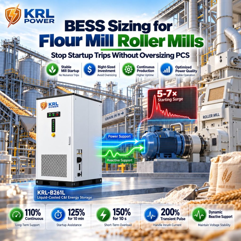
BESS sizing for flour mill roller mills starts with the motor-start event, not the battery's kWh label. A 55 kW, 400 V roller-mill motor can present about 417 kVA under a 6× direct-on-line (DOL) starting screen. KRL Power combines a defined PCS overload envelope with dynamic reactive-power support, giving flour mills a stronger way to manage short, heavy starts without buying peak capacity as if it were a permanent load.
A mill that trips on restart does not automatically need a six-times-larger PCS. It needs the starting current, duration, voltage dip, running load and available AC sources assessed together.
- One controlled process feeder: Start with KRL-B261L, rated 125 kW / 261 kWh. Its overload capability and dynamic reactive support can be coordinated with the approved starter and source-sharing arrangement.
- Several coordinated drives: Review KRL-B522L, rated 250 kW / 522 kWh when more continuous output, AC current headroom or overlapping process loads must be covered.
- Whole-plant or multiple-feeder operation: Compare KRL's 750 kW and 1 MW container configurations against the milling hall's continuous load and required backup duration.
The Roller Mill Starts, the PCS Trips—and Production Stops
A roller mill is not a smooth, predictable 55 kW load. Its motor draws a sharp current surge at energization, then continues to demand torque while the rolls accelerate. If the grinding passage retains material after an upstream interruption, the restart can become more demanding. On a weak AC bus, the same event can pull voltage down just as contactors, PLCs, conveying equipment and adjacent drives need stable power.
The cost is larger than a nuisance alarm. A failed restart can interrupt the feed sequence, stop pneumatic conveying, leave product trapped between process stages and force operators to restore interlocks across the line. An 80% battery state of charge does not prevent a PCS current-limit trip: stored energy and instantaneous AC output are different constraints.
Never treat a larger inverter as permission to force a jammed mill to restart. The roller-mill OEM's permissives, clearing procedure and torque limits still govern safe operation.
DOL current is not the same as normal running demand
Direct-on-line starting can draw several times a motor's full-load current. A 5–7× range is a useful first screen for some induction motors, but the actual multiplier depends on the motor design, supply voltage, starting condition and nameplate locked-rotor data. It is not a universal value for every roller mill.
The acceleration period must also come from the actual motor and drive arrangement. Do not assume every mill reaches speed in three, five or eight seconds. A current-versus-time trace, the permitted starting method and the motor's acceleration behavior give the PCS supplier a usable design basis. IEC 60034-12:2024 provides a relevant framework for induction-motor starting performance.
Voltage sag can trip the line before energy becomes a problem
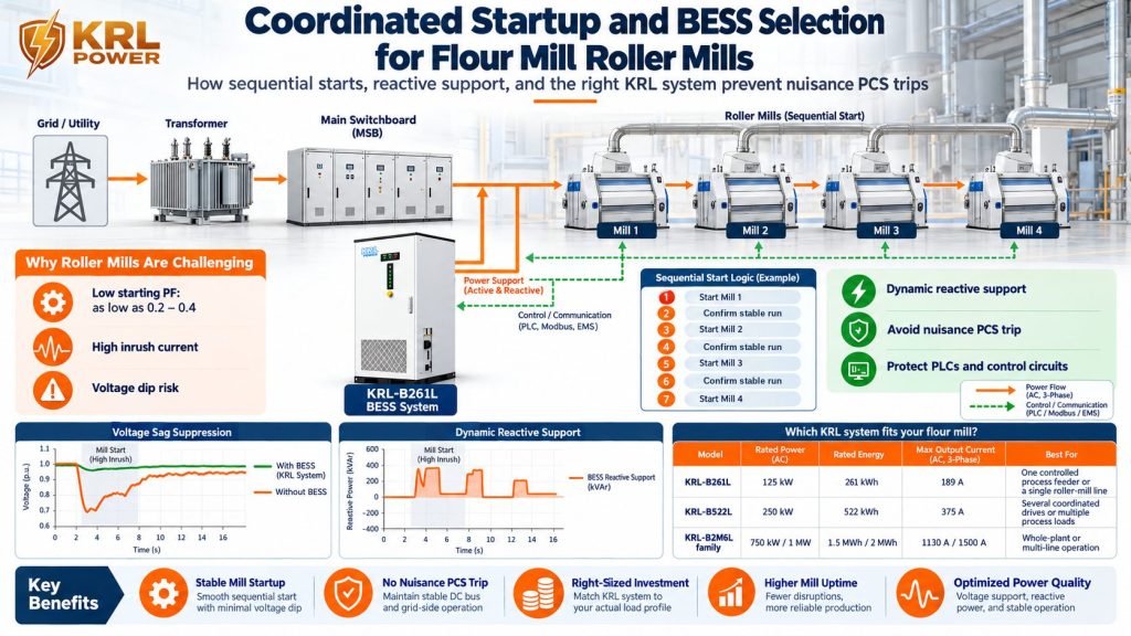
A DOL motor draws substantial reactive current when its starting power factor is low. The transformer, cables, switchgear, diesel alternator and grid-forming PCS all experience that changing demand. Voltage sag can release contactors or trigger VFD undervoltage protection even when the plant's active-power reading remains below the PCS's continuous kW rating.
The existing KRL guide to motor starts versus a 125 kW PCS is a useful companion, but flour mills need a more specific review of roll drives, start permissives, source impedance and grinding-line sequence.
Two PCS Sizing Mistakes That Blow Up a Flour Mill Budget
Mistake 1: choosing battery energy from an average meter reading
The kWh rating tells the buyer how much energy the battery stores. It does not certify the AC current available during the first cycles of a motor start. A 125 kW PCS can reach its current limit while the battery still has plenty of charge.
Compare four separate ratings: continuous kW, maximum AC current, overload capability by duration, and reactive-power capability in the intended operating mode. KRL's heavy-duty PCS provides 110% continuous operation, 125% overload for 10 minutes, 150% for 10 seconds and a 200% transient pulse, with dynamic reactive-power support. That defined overload envelope gives the design short-duration headroom without treating every locked-rotor peak as continuous output.
Mistake 2: buying a 600 kW PCS because the motor starts at 6× current
Multiplying motor nameplate kW by the locked-rotor current multiplier and calling the result a required PCS kW rating is a costly shortcut. Motor nameplate kW usually describes mechanical shaft output. Starting current and voltage determine apparent power in kVA; the starting power factor determines how that demand divides into active kW and reactive kVAr.
The PCS may not be the only AC source. Utility supply, a suitably rated diesel alternator and a coordinated starter can change how much of the transient the BESS must supply. A standalone BESS starting a DOL motor is a different duty from a BESS sharing the event with the grid or generator.
Utilisez le KRL 125 kW / 250 kW / plant-class comparison against the real operating envelope. Oversizing without a source-sharing study wastes capital; undersizing without a transient study leaves the trip unresolved.
Calculate the Starting Demand of a 55 kW Roller Mill at 400 V
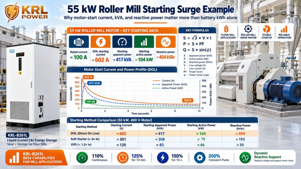
A transparent motor-start calculation is more useful than a quotation that simply says “heavy duty.” The worked example below estimates the electrical demand of one 55 kW motor and shows why kW, kVA, current and overload duration must be considered separately.
| Input for one roller-mill motor | Screening value |
|---|---|
| Rated mechanical output | 55 kW |
| Three-phase line voltage | 400 V |
| Assumed full-load efficiency | 93% |
| Assumed running power factor | 0.85 |
| Assumed DOL current multiplier | 6.0 × rated current |
| Assumed initial starting power factor | 0.25 |
Step 1 — estimate rated full-load current.
I_FL=(55,000)/(√3×400×0.93×0.85)≈100.4 A
Step 2 — estimate DOL starting current.
I_start=6.0×100.4≈602 A
Step 3 — convert current to three-phase apparent power.
S_start=(√3×400×602)/(1,000)≈417 kVA
Step 4 — split the apparent power into active and reactive demand. At the assumed starting power factor of 0.25:
P_start=417×0.25≈104 kW
Q_start=417×sqrt1-0.25^2≈404 kVAr
The result exposes the sizing trap: the motor's estimated starting demand is about 602 A and 417 kVA, while its initial active-power component under the assumed power factor is about 104 kW. The 417 kVA value is not a command to buy a 417 kW PCS. Nor should the starting event be assumed to come entirely from the battery. The system design assigns the transient across the chosen starter, KRL's overload response and dynamic reactive support, plus any utility or diesel contribution available in that operating mode.
KRL's 150% / 10-second capability and 200% transient pulse are important parts of the short-duration design. Sequential starts and source sharing prevent several motor surges from stacking into one larger event. Where battery-only DOL starting is required, use the actual motor-start waveform and the complete system topology to specify the duty.
Le KRL-B261L provides 125 kW / 261 kWh / 189 A; the KRL-B522L provides 250 kW / 522 kWh / 375 A. Their continuous ratings work alongside KRL's timed overload envelope. Select the product from the motor-start profile, source contribution and running load—not by multiplying motor kW by six and purchasing the same number in continuous PCS kW.
Do not apply the starting power factor a second time when calculating full-load current. It is already accounted for in the separate starting kVA-to-kW/kVAr split above.
Reduce the Starting Surge Without Sacrificing Roller-Mill Torque
Reducing current before it reaches the PCS can cost less than buying an oversized converter—but only if the motor still develops enough torque to accelerate under its actual load. A current limit that looks good on a specification sheet is useless if the roll drive stalls or remains in acceleration for too long.
| Starting strategy | Electrical effect | Flour-mill design check |
|---|---|---|
| Direct-on-line (DOL) | Highest initial current and strong starting torque | Use only when the source, motor data and switchgear can support the event |
| Star–delta | Reduces initial line current and starting torque | Confirm the reduced torque can accelerate the mill; check the transition disturbance |
| Soft starter | Ramps voltage/current during acceleration | Set the current limit against real load torque, motor heating and start duration |
| Variable-frequency drive (VFD) | Controls speed and torque ramp; input demand depends on drive design | Check overload class, input harmonics, DC-link behavior, motor cooling and restart interlocks |
| Sequential starting | Prevents several motor starts from overlapping | Permit the next drive only after the preceding drive and related process systems report healthy status |
Sequence the milling process, not just the electrical cabinets
If four mills receive a start command together, their current peaks can overlap. A proper restart sequence separates those events while preserving the required order for lubrication, dust extraction, conveying, feed gates, roll drives and downstream interlocks.
The control logic needs clear states: ready to start, drive at speed, feed permitted et fault reset complete. Arbitrary time delays alone do not prove that the process is safe to restart. The sequence must follow the mill OEM's requirements and be approved by the plant's controls engineer.
Use KRL dynamic reactive support to steady the AC bus
Roller-mill acceleration can impose a sharp reactive-power demand. KRL's dynamic reactive-power support (SVG mode) helps address that demand, while its 110% continuous, 125% for 10 minutes, 150% for 10 seconds and 200% transient pulse capability provides a defined overload envelope for short-duration events. Together with the selected starter and coordinated AC sources, these functions help limit voltage sag and support stable operation of PLCs, contactors and adjacent process equipment.
The result depends on the complete system design: starter ramp, source contribution, current-sharing arrangement and start sequence must match the measured mill duty. That is how the project uses KRL's capability to solve the actual problem instead of paying for a much larger PCS by default.
Select KRL BESS Around the Mill's Actual Feeder Duty
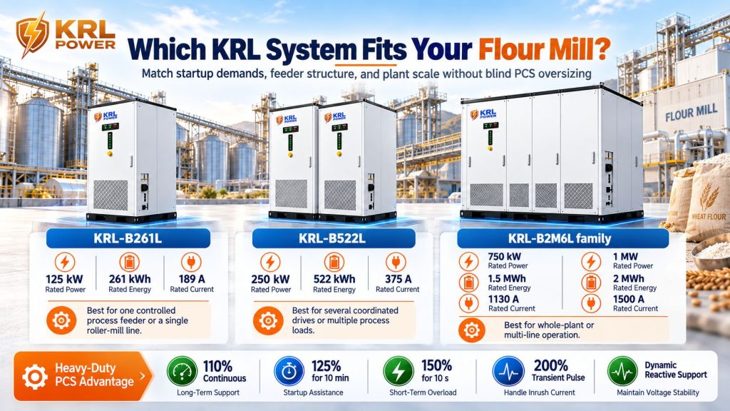
KRL's liquid-cooled battery systems combine defined power classes with a heavy-duty PCS overload envelope, dynamic reactive-power support and solar/diesel integration options. Start by matching continuous feeder power and backup duration to the product class; then design the starting event around current, kVA, overload duration and the available sources.
| KRL system | Rated AC output | Courant alternatif maximal | Capacité nominale de la batterie | Initial screening fit |
|---|---|---|---|---|
| B261L | 125 kW | 189 A | 261 kWh | One controlled process feeder with a verified start sequence |
| B522L | 250 kW | 375 A | 522 kWh | Larger feeder or several sequenced motors with coordinated source sharing |
| B2M6L family | 750 kW / 1,000 kW | 1,130 A / 1,500 A | 1.5 MWh / 2 MWh | Full process lines or multiple feeders after distribution-system review |
One controlled mill feeder: start with B261L
KRL-B261L combines 125 kW on-grid/off-grid output, 261 kWh rated energy, 189 Courant alternatif maximal, PV input up to 120 kW, and a diesel-generator port. It uses liquid battery cooling and has an IP65 battery protection grade—useful integration features for a flour-mill site combining storage, solar generation and an existing standby generator.
B261L is the first product to evaluate for a controlled feeder where the starter, restart sequence and available AC sources are coordinated. KRL's overload envelope and dynamic reactive support address the short-duration electrical stress; the start arrangement determines how the motor's full transient demand is shared across the system.
Several roll drives: move the review to B522L
KRL-B522L provides 250 kW, 522 kWh, 375 A maximum AC current, PV input up to 240 kW and a diesel interface. It offers a wider continuous power/current class for several coordinated drives or a larger running load.
The choice between two B261L cabinets and one B522L affects protection, feeder topology, control sharing, PV connections and installation work. Equal nameplate kW does not make the electrical arrangements interchangeable. Review KRL's two-B261L versus single-B522L comparison and the integrated 250 kW solar-storage-diesel configuration when the existing generator remains part of the plant's production-support plan.
A full milling hall needs a plant-scale review
Four 55 kW motors represent 220 kW of rated shaft output before aspirators, elevators, compressors, lighting or packing equipment. At 93% motor efficiency, those four motors alone require about 237 kW of electrical input when operating at simultaneous rated shaft load. That leaves little active-power margin in a 250 kW PCS for the rest of the process.
If the entire hall must operate battery-only, review KRL's 750 kW / 1,5 MWh ou 1 MW / 2 MWh container configuration. Their rated AC currents are 1 130 A et 1,500 A, so the transformer, cables, protection and busbars must be designed for the actual 400 V installation. Use KRL's plant-class escalation guide to compare the cabinet and container classes.
Four 55 kW Roller Mills: Make the Right Procurement Decision
Consider a flour line with four 55 kW roller-mill motors on a 400 V supply. The wrong quotation either sizes the battery from an average meter reading or multiplies every motor's kW by six and sells a huge PCS. KRL's overload envelope and dynamic reactive support provide a more disciplined basis when combined with an approved restart sequence and coordinated AC sources.
Case 1: all four motors start DOL on the same weak islanded bus. Their current peaks overlap while other process loads remain connected. The design must account for the combined transient and source impedance. Treating the combined inrush as a permanent PCS kW requirement is not a sound substitute for a start-sequence and source-sharing study.
Case 2: the mills restart in an OEM-approved sequence with suitable drives. The control schedule reduces overlapping peaks. KRL's 150% / 10-second overload capability, 200% transient pulse and dynamic reactive support give the system short-duration headroom while the starter and available sources support acceleration. The key sizing question becomes the largest controlled start plus the load already running.
Case 3: utility or diesel generation shares the start. A coordinated source arrangement reduces the transient contribution demanded from the BESS. KRL supports the event within its defined operating envelope, allowing the project to size around the actual duty rather than buying a 600 kW PCS simply because one motor's starting current is six times its full-load current.
500 t/day flour-mill benchmark: For a wheat-processing line with four 55 kW roller mills, the KRL 125 kW / 261 kWh system was selected around the operating duty, coordinated restart sequence, PCS overload envelope and dynamic reactive support. With 110% continuous, 125% for 10 minutes, 150% for 10 seconds and 200% transient pulse capability, the design met the agreed start duty without basing the quotation on an oversized 600 kW PCS. The project benchmark recorded 45% lower initial investment than the oversized alternative. The commercial lesson is direct: engineer the transient and sequence; do not pay for idle PCS capacity to cover a few seconds of surge.
| Procurement question | Evidence to collect | Why it matters for KRL selection |
|---|---|---|
| Which motors start together? | OEM-approved start/permissive matrix | Establishes whether current peaks overlap |
| Which source is connected during each start? | Single-line diagram and control sequence | Defines battery-only versus shared-source duty |
| What load is already running? | Feeder trend and, where needed, a faster event waveform | Shows the PCS headroom available before the start |
| What does each drive draw during acceleration? | Motor/drive data and current-versus-time trace | Defines the required kVA, current and duration |
| How long must production continue? | Critical-load kW and required runtime after usable-energy deductions | Separates PCS power sizing from battery-energy sizing |
KRL's 300 kW textile-factory hybrid microgrid assessment addresses the same purchasing boundary in another industry: confusing a power constraint with an energy constraint.
Size Battery kWh After PCS Current and Starting Method Are Settled
A motor start that lasts a few seconds rarely determines the full battery-energy requirement by itself. Maintaining production through a prolonged grid outage often does.
Start with the protected AC load and the required backup period. Then account for the usable state-of-charge window, conversion losses, auxiliary consumption, ageing margin and any required reserve. Dividing rated battery kWh by motor shaft kW is not a reliable runtime calculation.
A mill that keeps its roll drives on the utility or diesel source may need the BESS to support controls, transfer bridging and selected critical loads. A plant that must run the entire grinding line on battery power for two hours needs a very different energy budget. KRL's factory diesel-support assessment explains how to separate the operating boundary from the stored-energy requirement.
Use this order: verify the starting method → calculate current, kVA and voltage dip → determine the BESS share → select continuous PCS kW/current → size delivered backup energy → verify installation and controls.
Factory Acceptance and Site Tests That Protect Production
A 250 kW nameplate alone cannot show whether a 400 V mill will restart cleanly after a power disturbance. Require evidence at both factory acceptance testing (FAT) and site acceptance testing (SAT).
- Verify motor nameplates and feeders. Record rated output, voltage, full-load current, efficiency, starting method and permitted operating mode for each roller-mill motor.
- Capture current and acceleration time. Record the actual start waveform, including the OEM-approved restart condition. Never force a jammed mill to restart simply to test the PCS.
- Test each source mode. Validate battery-only, utility-supported and diesel-supported operation separately. Record point-of-common-coupling voltage, phase current, frequency, active/reactive power, SOC and PCS alarms.
- Check controls and protection. Verify VFD undervoltage settings, contactor behavior, grid-loss transfer, anti-islanding, generator synchronization, reverse-power protection and emergency shutdown.
- Demonstrate sequential restart. Confirm that feed gates, roll drives, conveyors, extraction fans and safety interlocks return in the approved order without a cumulative current spike.
- Review flour dust and equipment siting. Check combustible-dust zone classification and installation location before approving switchgear, inverter placement and cable routes. Apply locally adopted rules and IEC 60079-10-2:2026 where relevant; an IP65 battery compartment is not, by itself, approval for an explosive atmosphere.
Include KRL's 110% continuous, 125% for 10 minutes, 150% for 10 seconds and 200% transient pulse ratings, together with dynamic reactive-power support, in the agreed FAT/SAT criteria. Test the selected start sequence under agreed site conditions and record current, voltage, frequency, active/reactive power and PCS alarms.
Stop Paying Twice for the Same Roller-Mill Starting Problem
Oversized PCS hardware consumes the project budget. Undersized PCS hardware leaves the mill facing the same restart fault—and the production loss that follows. The deciding variable is the motor-start profile at the AC bus, not a blanket multiplier applied to motor kW.
KRL's B261L, B522L and 750 kW / 1 MW systems provide clear power classes, liquid-cooled battery integration, solar/diesel interfaces and a heavy-duty PCS overload envelope. Pair that capability with dynamic reactive support and coordinated motor starts, and flour-mill EPCs have a practical route to protecting production without blindly oversizing the PCS.
A useful technical review starts with the 400 V single-line diagram, motor nameplates, starter/VFD model numbers, permitted start sequence, recorded feeder current and required battery-only runtime. These details turn a generic cabinet quote into an equipment decision tied to the plant's actual duty.