
Power factor correction using a C&I BESS inverter gives industrial plants a direct way to attack low-PF and reactive-energy penalties—provided the PCS has four-quadrant control and enough kvar headroom for the measured load. KRL Power combines dynamic SVG support with peak shaving, energy arbitrage and backup capability, turning one industrial asset into a power-quality tool and a cost-control platform.
A low power factor drains margin twice: it drives higher current for the same useful kW, consumes transformer and feeder capacity, and can trigger additional charges under the utility tariff. If reactive-energy or low-PF charges keep appearing on the bill, replacing capacitors without fixing the control problem is paying twice. KRL’s South Africa factory PF-correction solution shows the application context; the KRL-B261L, installation de 125 kW / 261 kWh provides a concrete C&I platform to assess; and the B261L, B522L and B2M6L selection guide helps match system class to the actual site duty.
Every Low-PF Penalty Is Margin Your Factory Gives Away
Mining, metallurgy, cement production, plastic injection moulding and other heavy industrial processes combine motors, transformers, pumps, compressors, welding equipment and non-linear loads. Those assets can draw substantial reactive power, particularly when operating at partial load, starting or changing production rate. If the incoming supply’s power factor falls below the utility’s tariff threshold, the bill can include a low-PF surcharge, reactive-energy charge or a demand charge based on kVA.
The threshold is not identical across every country, customer class or tariff. Eskom’s published power-factor guidance identifies 0.96 as the relevant threshold for its additional reactive-power fee. Kenya’s electricity tariff guidance describes a 0.90 threshold and a surcharge process for qualifying consumers after written notice. Nigerian industrial customers must check the tariff and connection terms that apply to their specific DisCo or market arrangement. A sales claim that every African plant is penalised at 0.90 would be wrong; the actual bill and tariff schedule set the rule.
Start with the bill line that is hurting the margin. Separate kVARh or low-PF charges from energy charges, maximum-demand fees, fixed charges, taxes and fuel adjustments. Then calculate which part a PF-correction system can remove. A credible proposal isolates the recoverable cost and shows the CFO the arithmetic; it does not pretend reactive compensation erases unrelated charges.
For a site whose PF falls from 0.80 to 0.72, the cost can escalate quickly if its tariff penalises reactive energy or kVA demand. The outline’s 2 MVA-class example estimates a monthly penalty of USD 8,000–15,000. Treat that as a scenario to test against a real invoice, not a universal tariff promise. A defensible savings estimate uses the customer’s actual billing period, meter readings, tariff clause and measured load profile.
Calculate the Reactive Power the Plant Must Stop Importing
Power factor correction must begin with measured active power and reactive power, not the transformer nameplate alone. A 2 MVA transformer does not prove that the plant is drawing 2 MVA continuously. Use the utility point-of-connection meter or a suitable power-quality analyser to record kW, kvar, kVA, voltage, current, true power factor and harmonic distortion over representative production shifts.
For a predominantly sinusoidal load, the first-pass compensation requirement can be estimated as:
Qc = P × [tan(arccos(PF₁)) − tan(arccos(PF₂))]
Here, P is measured active load in kW, PF₁ is the present power factor and PF₂ is the target. The result Qc is the approximate reactive power required in kvar. Where harmonic distortion is material, do not rely on displacement power factor alone: use true PF and harmonic measurements to define the correction strategy.
Consider a measured 1,200 kW load with a present PF of 0.80 and a target PF of 0.96. The initial estimate is about 550 kvar of compensation. That is a starting calculation, not a final equipment rating. The engineer still has to account for load variation, the point of connection, voltage limits, existing capacitors, harmonic filters, leading-PF risk and the PCS’s available apparent-power capacity.
The same calculation should be run across operating states: full production, low production, large motor starts, furnace or welder cycles, night shift and shutdown. A single monthly average can conceal the exact intervals that trigger the surcharge. The best correction target is the one that complies with the tariff without pushing the plant into excessive leading power factor during light load.
Stop Paying for APFC Banks That Cannot Keep Up With the Load
Automatic power factor correction (APFC) still has a place when loads are stable and the capacitor stages are correctly sized. The trouble starts when kvar demand swings faster than the bank can respond or when harmonics stress the capacitors. At that point, the old fix can turn into a recurring maintenance bill while the penalty remains on the invoice.
Stepwise correction leaves a gap. A contactor-switched bank supplies fixed kvar increments. Between steps, the plant can remain under-compensated; after a sudden load drop, the last stage may temporarily leave too much capacitance connected. That does not mean every APFC bank is defective. It means the switching response, step size and controller settings must suit the load profile.
Harmonics need a designed response. Variable-frequency drives, rectifiers, induction furnaces and other non-linear loads can produce harmonic currents. Capacitors interact with system inductance, and an unsuitable combination can create resonance or amplify harmonic stress. The result can include overheating, shortened capacitor life, blown fuses or failed switching components. Replacing capacitors without measuring the harmonic environment often repeats the same failure.
Maintenance costs accumulate. Capacitors age, contactors wear, fuses operate and connections loosen under heat and switching duty. A correction cabinet that is not inspected and tested may show a healthy controller display while delivering less kvar than its nameplate suggests.
This is not a blanket instruction to remove every capacitor bank. The test is whether the installed APFC tracks actual kvar demand without lag, over-compensation or harmonic trouble. A healthy bank can remain in a coordinated design. Where it repeatedly misses the load or fails under harmonic stress, KRL’s dynamic reactive-power control offers a stronger route than buying the same failing fix again.
KRL Four-Quadrant PCS: Turn the BESS Into a Dynamic SVG Asset
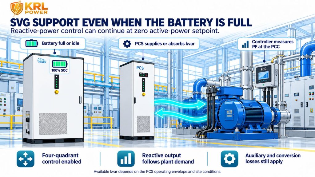
A BESS that only charges off-peak and discharges at peak is leaving part of its value unused. Four-quadrant PCS operation controls active power (P) and reactive power (Q) in both directions. Within its operating envelope, the converter can charge or discharge while supplying or absorbing kvar. That is how KRL can address power-factor penalties as well as energy costs.
Here is the commercial edge: KRL’s four-quadrant PCS and dynamic SVG function can respond to measured plant demand instead of waiting for a contactor to switch another fixed capacitor step. The KRL configuration supports 10–20 kHz switching and response below 5 ms. At the agreed point of connection, the controller tracks actual PF or kvar against the target and adjusts the PCS command within its configured operating envelope.
When the battery is at 100% SOC—or the site is neither charging nor discharging—the configured PCS can still provide reactive compensation in zero-active-power SVG operation. Where the KRL PCS has enough kvar headroom, the plant can use the converter it already bought instead of automatically adding a separate SVG cabinet. Correct CT placement, metering, control settings and commissioning make that capability work at the utility meter.
The available reactive power is limited by the PCS rating and its current envelope. Where active output is high, some converter capacity is already being used for kW, leaving less headroom for kvar. The P–Q relationship is bounded by the converter’s apparent-power rating: S² = P² + Q². Therefore, simultaneous peak shaving and PF correction must be checked at the worst coincident operating point, not judged from two separate nameplate numbers.
The control target can be set around PF 0.98–0.99 where the utility tariff, plant load, PCS capacity and protection settings allow it. The target must also prevent leading PF when inductive load falls away. The correct promise is measured correction within the agreed operating envelope, not an unconditional claim that every plant will sit at 0.99 under every possible load.
Size the KRL System Around Both kW and kvar
The right C&I BESS is not selected by battery energy alone. The design must cover the site’s active-power duty, reactive-power target, operating duration, maximum AC current and the utility point-of-connection limits. A large kWh number cannot compensate for a PCS that lacks the required current or kvar capability at the same moment.
KRL’s product classes provide a practical starting shortlist:
| KRL system class | Rated active power | Capacité nominale de la batterie | Best first screening question |
|---|---|---|---|
| KRL-B261L | 125 kW | 261 kWh | Can one cabinet cover the plant’s required active-power duty while retaining the kvar headroom needed at the PCC? |
| KRL-B522L | 250 kW | 522 kWh | Do larger simultaneous loads, a higher peak-shaving target or a greater reactive requirement justify the next class? |
| KRL-B2M6L family | 750 kW / 1,000 kW configurations | 1.5 MWh / 2 MWh configurations | Does the plant require multi-feeder or plant-scale power, energy and reactive support? |
Consultez le KRL C&I ESS class comparison alongside the site’s measured duty. The B261L is a 125 kW / 261 kWh liquid-cooled system with a 400 V AC interface and a maximum AC current of 189 A. The KRL-B522L 250 kW / 522 kWh system provides a maximum AC current of 375 A. The KRL B2M6L 750 kW / 1 MW class comparison covers larger plant-scale configurations. These ratings help shortlist the hardware; the final PF correction rating must still be confirmed against the actual PCS P–Q capability and the connection design.
A good specification lists the active-power demand and kvar requirement separately. It also states whether the system must correct PF while charging, discharging, at zero active power, during generator operation or while solar output changes. The agreed duty matrix prevents a quote from counting the same converter capacity twice.

Combine PF Correction With Peak Shaving, Arbitrage and Backup
Reactive compensation can improve the economics of a BESS project, but it should be calculated as one revenue or cost-avoidance stream within a wider operating model. The main value buckets are distinct:
- Avoided PF or reactive-energy penalties: calculate from the utility’s tariff formula and the measured billing baseline.
- Reduced kVA demand charges: count this only where the tariff actually bills kVA demand or includes a related demand clause.
- Peak shaving: calculate the reduction in billed kW or kVA peak under the customer’s tariff and demand interval.
- Energy arbitrage: model charge energy, discharge energy, tariff spread, conversion losses, battery degradation and operating limits.
- Backup value: quantify critical-load protection only when transfer architecture, islanding capability, reserve SOC and protected circuits have been designed for that duty.
Do not add every possible benefit as though each one were guaranteed to occur at full value every month. Some operating modes compete for the same PCS capacity or battery energy. For example, discharging aggressively for peak shaving may leave less active-power headroom for simultaneous reactive compensation. An EMS dispatch plan should prioritise the agreed PF target, demand limit, reserve SOC and tariff windows instead of pursuing each objective independently.
When the PF penalty is material and the site also captures demand and energy savings, stacking those benefits can move a well-matched project toward the 2–3-year payback target. That outcome has to be earned in the numbers, not promised by a slogan. Show base, conservative and upside cases with tariff evidence, measured load data, system cost, usable energy, efficiency, degradation, maintenance and financing assumptions visible. The CFO should see which savings create the return and which depend on operating discipline.
For broader project sizing, KRL’s C&I energy storage systems guide et Présentation générale des systèmes BMS, PCS et EMS provide useful internal background on the system components behind the operating strategy.
Commission the System Against the Utility Meter, Not a Dashboard Screenshot
A power-factor target is only meaningful if the control system is measuring the right point. CTs installed on the wrong side of a load, a reversed CT polarity, phase mapping errors or a target that ignores the utility meter boundary can make a controller chase the wrong signal. Before enabling automatic correction, the commissioning plan should verify the measurement location and direction of active and reactive power.
A practical commissioning sequence includes:
1. Record a baseline across representative shifts: kW, kvar, kVA, true PF, voltage, current and harmonic spectrum at the point of common coupling (PCC).
2. Verify CT ratio, polarity, phase sequence, voltage reference and communication between the meter, EMS and PCS.
3. Confirm the PCS’s permitted P–Q envelope at the intended voltage, temperature and active-power output.
4. Test low-load operation as carefully as full production. The controller must reduce or reverse reactive output when the plant’s inductive demand falls.
5. Run peak-shaving and PF correction together at the expected coincident peak. Confirm the PCS does not exceed its current or apparent-power envelope.
6. Check existing APFC stages, detuned reactors and harmonic filters. Keep suitable equipment where it helps; isolate or redesign components that create an unsafe resonance or control conflict.
7. Compare the utility meter’s interval data before and after commissioning. The monthly bill, not a single instantaneous PF display, confirms whether the tariff charge was reduced.
The plant should also agree on the control hierarchy: which function takes priority when the BESS is close to its current limit, the battery is at its SOC boundary, the generator is online, or the plant moves into islanded operation. A well-integrated system handles these transitions deliberately instead of allowing separate controllers to fight each other.

Apply the Same Engineering Logic Across Africa, the Middle East and Southeast Asia
South Africa: Check Eskom’s PF and reactive-energy rules
Eskom’s published power-factor guidance identifies 0.96 as the threshold relevant to its additional reactive-power fee. The project team should still verify the customer’s tariff category, billing period and applicable clauses rather than assuming every site is charged in the same way. For a plant with a persistent PF problem, compare the interval-level kvar demand and invoice charge with the correction target. KRL’s South Africa PF-correction application is the most relevant internal starting point.
Nigeria: Use the actual DisCo or market tariff
Nigeria’s electricity market and tariff arrangements can vary by DisCo, customer class and applicable market rules. Do not copy a surcharge percentage from another country or assume that every industrial customer receives the same penalty. Use the customer’s current bill and the applicable tariff document to identify whether the cost is based on reactive energy, PF, kVA demand or another provision. KRL’s custom energy storage solutions provide a route to assess the site’s combined power-quality and reliability requirements.
Kenya: Check the notice and surcharge conditions
Kenya’s electricity tariff-setting guidance describes a power-factor threshold of 0.90 and a surcharge mechanism for relevant customers following written notice if the PF is not improved. The exact treatment must be checked against the applicable tariff and the customer’s current contractual conditions. Set the PCS target to meet the real connection requirement while avoiding leading PF at low load; do not simply copy a 0.99 setpoint from another installation.
Across the Middle East and Southeast Asia, apply the same process: obtain the current tariff, identify the actual PCC measurement, measure the plant’s kvar profile, and size the PCS for coincident active and reactive duty. A country name is not a substitute for the tariff clause.
Stop Paying the Same Reactive-Power Penalty Every Month
Replacing failed capacitors without diagnosing the load profile can leave the plant with the same penalty and another maintenance bill. Buying a BESS without checking its P–Q envelope can create the opposite problem: a battery that supports peak shaving but cannot supply the required kvar at the same operating point.
KRL Power’s four-quadrant PCS and dynamic SVG capability let industrial operators tackle reactive penalties without treating the BESS as a one-job asset. The same system can support active-power management and reactive compensation, with peak shaving, energy arbitrage and backup planned around the plant’s actual duty. One coordinated system can do more useful work against the factory’s electricity costs.
For an engineering review, the most useful starting package is the latest electricity bill, the tariff schedule, a representative interval-data export, the transformer and PCC details, the existing APFC or filter specification, and the expected peak-shaving and backup duties. Those inputs let the system team separate avoidable PF penalties from other charges and compare the required kvar against the available KRL PCS capacity.
Bring the latest bill, tariff schedule and load profile to KRL Power for a project-specific review of penalty drivers, target PF, required kvar, PCS class and realistic savings range. The result is a clearer equipment decision—not another generic promise that every charge will disappear.