 Skip to content

Engineering review by Liu, KRL Power R&D Director—20 years of C&I energy-storage engineering experience, formerly in Huawei R&D.
A commercial customer has requested a solar-plus-storage system for a 130 kVA load that must remain operational for seven continuous hours. The preliminary brief mentions one 250 kW inverter, two 522 kWh battery cabinets and a 219.45 kWp photovoltaic array built from 550 W modules. The system is intended for commercial off-grid or backup operation, and the customer does not currently have a diesel generator.
At first glance, the equipment list appears reasonable. However, a reliable quotation cannot be based on kVA and operating hours alone. The decisive engineering questions are the load’s real kW, power factor, motor-starting demand, phase balance, daily load profile, required reserve state of charge and the energy that must remain available at end of battery life.
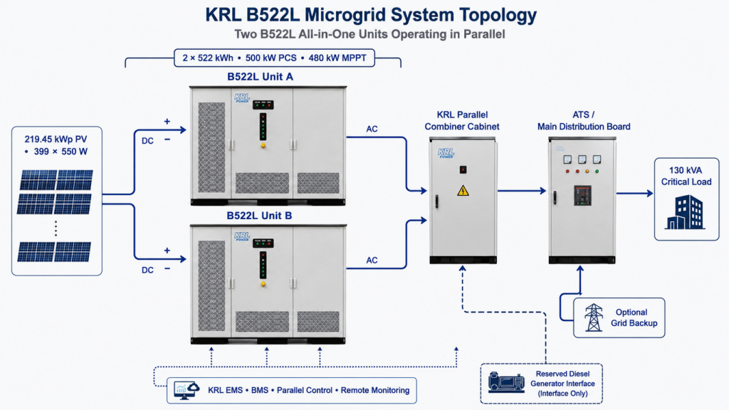
The KRL B522L is not a battery-only expansion cabinet. Each unit is a complete solar-storage-grid-diesel microgrid system integrating a 522 kWh battery, 250 kW PCS, 240 kW MPPT, BMS and EMS. Two complete B522L units connected in parallel therefore provide 500 kW of PCS power, 1.044 MWh of nominal battery energy and 480 kW of total integrated MPPT capacity. Their AC outputs must be combined through an engineered parallel combiner cabinet before the main distribution system.
This article explains how KRL Power would review that parallel architecture before releasing a firm solution. The goal is not to oversell the system. It is to show where the proposed configuration is strong, where its seven-hour autonomy is conditional and which site data must be confirmed before manufacturing.
What the Customer Is Asking KRL Power to Supply
The project brief contains the following technical and commercial requirements:
- Commercial and industrial off-grid or backup-power application.
- 130 kVA load operating continuously for seven hours.
- One 250 kW bidirectional inverter or PCS section.
- Two 522 kWh battery cabinets, providing 1,044 kWh nominal storage.
- A 219.45 kWp PV array using 399 modules rated at 550 W each.
- No existing diesel generator.
- Customer-managed local installation and commissioning.
- FOB port logistics rather than delivery from a local African warehouse.
- Quotation and settlement in USD, with an indicative local-currency conversion.
- Proposed payment structure of 50% advance payment and balance before shipment.
One commercial detail must be corrected before the quotation is released. The brief labels the project as a South Africa installation, while the warehouse and currency notes refer to Nigeria and the Nigerian naira. Country, destination port, importer of record and settlement currency affect freight, customs, grid requirements, environmental design and local approvals. KRL should therefore keep the engineering concept country-neutral until the customer confirms the final installation country and port.
The First Engineering Check: 130 kVA Is Not Automatically 130 kW
Apparent power in kVA and real power in kW are related by power factor:
Real power (kW) = Apparent power (kVA) × Power factor
For a 130 kVA load, the seven-hour energy requirement changes materially with power factor:
| Assumed Power Factor | Real Load | Seven-Hour Energy | Estimated Runtime from 883 kWh AC Energy |
|---|---|---|---|
| 0.80 | 104 kW | 728 kWh | 8.49 hours |
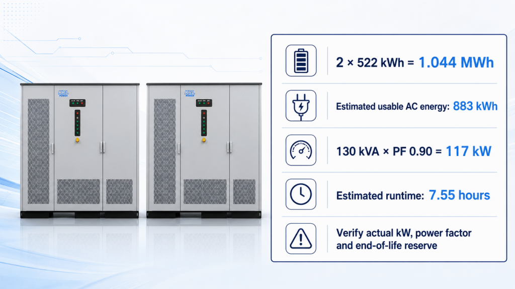
| 0.90 | 117 kW | 819 kWh | 7.55 hours |
| 0.95 | 123.5 kW | 864.5 kWh | 7.15 hours |
| 1.00 | 130 kW | 910 kWh | 6.79 hours |
Two 522 kWh cabinets provide 1,044 kWh of nominal DC energy. If an initial design calculation uses 90% usable depth of discharge and 94% DC-to-AC efficiency, the estimated beginning-of-life AC energy is:
1,044 kWh × 0.90 × 0.94 ≈ 883 kWh
This value does not yet include auxiliary consumption, high-temperature derating, cable losses beyond the simplified allowance, reserve SOC, cell imbalance or future capacity degradation. Therefore, two 522 kWh cabinets can support seven hours when the measured real load is around 115–117 kW, but the margin is tight. If the load remains near 130 kW, the proposed battery capacity does not provide a dependable seven-hour guarantee.
KRL should obtain at least seven days of 15-minute kW, kVA and power-factor data. Where motors, compressors, pumps or HVAC equipment are present, the customer should also provide the largest motor rating, starting method and simultaneous-start sequence. This prevents the common mistake of sizing energy correctly while underestimating instantaneous power.
What Two Complete B522L Units Change
Each B522L contains its own 250 kW bidirectional PCS. Connecting two complete units in parallel produces 500 kW of total PCS capacity. The EMS can limit operating power to the actual 130 kVA load, while the additional PCS headroom can serve several engineering purposes:
- Support short-duration motor-starting or transformer-inrush demand.
- Maintain voltage during sudden load steps in off-grid mode.
- Allow PV energy to support the load while surplus power charges the battery.
- Avoid continuous operation near the PCS thermal limit.
- Provide unit-level redundancy and reserve capacity for future load expansion, subject to the approved parallel-control strategy and battery limits.
The final judgement depends on the PCS overload curve, battery C-rate, site temperature, surge profile and the parallel-control logic. The final submittal should include total and per-unit rated power, overload duration, short-circuit contribution, black-start sequence, synchronization logic, communication redundancy and three-phase unbalance limits. KRL should also confirm that the customer accepts a 500 kW installed PCS rating even though the present load is much lower.
Recommended KRL Architecture
The recommended KRL architecture uses two complete B522L solar-storage-grid-diesel microgrid units operating in parallel. Each unit provides 522 kWh battery energy, a 250 kW PCS, 240 kW integrated MPPT with two routes, grid-connected and off-grid operation with seamless switching, integrated BMS/PCS/EMS, liquid cooling, an IP65 battery cabinet and RS485/WiFi/4G communications.
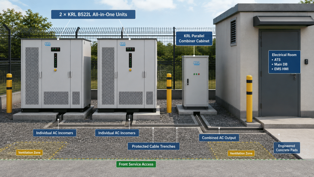
The two B522L AC outputs must not be joined directly at an unengineered site bus. Each output should enter a dedicated KRL parallel combiner cabinet with individual incomer protection, busbar sizing, metering, isolation, interlocking and coordinated protection. The combiner output then connects to the ATS/main distribution board and the 130 kVA critical-load bus. The optional grid connection and any future diesel-generator interface must follow KRL's approved synchronization and switching design.
The resulting system should include:
- Two complete 522 kWh KRL B522L all-in-one microgrid units.
- Two integrated 250 kW PCS sections, providing 500 kW total installed PCS capacity.
- Two integrated 240 kW MPPT sections, providing 480 kW total MPPT capacity.
- A KRL parallel combiner cabinet with protected incomers, common busbar, metering and isolation.
- Master-slave or peer-to-peer EMS coordination for PV priority, charge control, reserve SOC, synchronization and load sharing.
- ATS/main distribution, grid interface and reserved diesel-generator interface according to the confirmed operating mode.
- DC/AC isolation, surge protection, earthing, emergency stop and fire-safety interfaces.
- Remote monitoring through RS485, WiFi or 4G, depending on site communications.
For more product information, review the KRL B522L 250 kW / 522 kWh system and the KRL commercial and industrial ESS portfolio.
Engineering the 219.45 kWp PV Charging System
The PV quantity is mathematically clear:
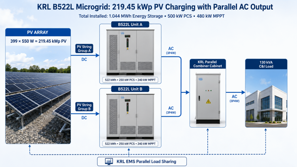
399 modules × 550 W = 219.45 kWp
The two B522L units provide 480 kW of total integrated MPPT capacity, so the proposed 219.45 kWp array does not require an external PV inverter. However, module count alone does not prove electrical compatibility. Final string design requires the selected module’s Voc, Vmp, Isc and temperature coefficients, together with each unit's MPPT voltage window, route-current limit and the minimum site temperature.
An illustrative arrangement is 21 strings of 19 modules. The string groups can be divided between B522L Unit A and Unit B—for example, 11 strings and 10 strings—while respecting the available MPPT routes and keeping route currents within limits. This is a planning concept only. KRL must run the cold-temperature Voc, current, route-allocation and unit-balancing calculations before releasing the string schedule.
The array’s daily energy also depends on location, orientation, shading, soiling and weather. Using a preliminary range of 4.5–5.5 peak-sun-hours and a performance ratio of 0.78–0.82 gives roughly 770–990 kWh per day. A representative 5.0-hour, 0.80-performance-ratio case produces about 878 kWh per day. That may replenish the energy used by a 117 kW load over seven hours, but it leaves little margin for daytime consumption or poor-weather recovery.
Because there is no diesel generator, the customer must decide how the system behaves after several low-solar days. Options include retaining an available grid connection for backup, increasing PV and storage after an energy simulation, shedding noncritical loads or reserving a future generator interface. A battery is an energy buffer; it is not an unlimited energy source.
Operating Modes That Should Be Programmed
Solar-Priority Daytime Operation
PV power first supports the active load. Remaining PV power charges the battery within cell, BMS and MPPT limits. The EMS prevents battery overcharge and limits power when the PV array, load and battery conditions do not permit full output.
Battery Backup Operation
When the grid is unavailable—or in a fully off-grid installation—the PCS establishes the AC bus and the battery supports the selected critical loads. Reserve SOC should be set according to the customer’s acceptable outage risk, not simply reduced to the lowest possible value to claim a longer runtime.
Recovery After an Extended Outage
When solar energy returns, the EMS must balance live load against battery recovery. If the entire PV output is consumed by the facility, battery recharge will be slow or impossible. The commissioning plan should therefore define load-shedding priorities and a minimum recharge target before noncritical loads are restored.
Site Layout, Installation and Customer Responsibilities
The customer states that its team can install and commission the equipment. This can reduce local service cost, but it does not remove the need for an approved engineering package. KRL should provide the final single-line diagram, equipment arrangement, foundation loads, cable schedule, protection settings, earthing requirements, communications map, I/O list, FAT records and commissioning checklist.
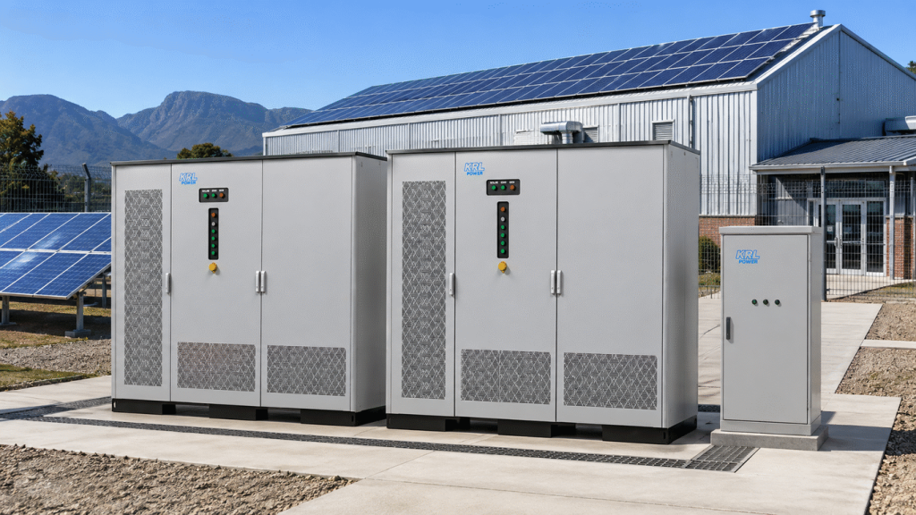
The customer still needs to confirm whether the B522L units and combiner cabinet will be installed indoors or outdoors, the altitude, minimum and maximum temperature, coastal-corrosion exposure, rainfall and flood level, dust conditions, drainage, fire access, cable routes, site lighting and local approval requirements. The concept layout uses two outdoor IP65 B522L units and a protected parallel combiner cabinet on engineered concrete pads. The ATS, main distribution and EMS HMI should be located in a dry, access-controlled electrical room unless KRL approves an outdoor enclosure arrangement.
FOB Logistics and Commercial Boundaries
Under FOB terms, KRL and the buyer must identify the named port in the contract. KRL’s normal responsibility includes manufacturing, factory testing, export packaging, inland transport to the named Chinese port, export clearance and loading on board, subject to the signed quotation. The buyer normally arranges main sea freight, marine insurance, destination customs, duties, inland delivery, unloading and local installation.
If settlement is in USD, a naira or rand conversion should be shown only as a dated reference because the local-currency value changes with the exchange rate. The binding contract amount should remain the agreed USD amount. The proposed 50% advance payment and balance before shipment must also be written into the proforma invoice together with the production schedule, FAT release point and shipping-document process.
Information KRL Needs Before a Firm Proposal
Before KRL freezes the BOM and warranty boundary, the customer should provide:
- Confirmed country, installation address, destination port and importer of record.
- Seven days of kW, kVA, power-factor and phase-current data at 15-minute intervals.
- Single-line diagram, voltage, frequency, earthing system and short-circuit level.
- Critical-load list, motor ratings, starting methods and permitted load shedding.
- Required autonomy at beginning and end of battery life.
- PV module datasheet, available area, orientation, tilt, shading and cable distance.
- Grid availability and whether export, zero-export or pure off-grid operation is required.
- Indoor/outdoor location, temperature, altitude, humidity, dust, corrosion and flood data.
- Local fire, electrical, structural and utility interconnection requirements.
- Installation scope, lifting plan, tools, test instruments and remote-support expectations.
Engineering Conclusion
Two complete KRL B522L units, a KRL parallel combiner cabinet and a 219.45 kWp PV array form a credible starting point for this 130 kVA commercial backup project. The parallel system provides 500 kW of installed PCS capacity, 1.044 MWh of nominal storage and 480 kW of total integrated MPPT capacity. The EMS should limit and share power according to the actual load, while the battery energy can meet a seven-hour target when the real load is close to 117 kW and site derating is modest.
It should not yet be sold as an unconditional seven-hour solution. If the actual load approaches 130 kW, if large motors start simultaneously, or if end-of-life autonomy is mandatory, the storage capacity or supported-load strategy must be adjusted. KRL Power’s next step is a measured-load review and a site-specific energy simulation, followed by a final SLD, BOM, control philosophy and USD FOB quotation.
