 Skip to content
Egypt industrial battery storage system projects should never be sized from MW alone. A factory buyer in Alexandria approached KRL Power asking for a 2MW industrial battery system. After technical clarification, the real requirement became clear: approximately 4MW of available grid power, an existing 500kW solar PV system, planned PV expansion toward 2MWp within six months, and at least eight hours of backup for the buyer's own factory.
This is exactly the type of project where simply quoting a 2MW battery can create an expensive sizing error. MW defines how much instantaneous power the PCS can deliver; MWh determines how long the battery can support the required load. KRL Power therefore recommends starting from the customer's critical-load profile, outage duration, PV architecture and diesel strategy before finalizing the commercial quotation.
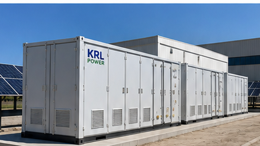
Based on the information currently available, the recommended Phase 1 platform is two KRL 1MW/2MWh all-in-one ESS units connected in parallel through an AC combiner/PCC cabinet, providing 2MW combined PCS power and 4MWh nominal battery energy. The same platform can support PV self-consumption, peak shaving, fast backup, generator-assisted long-duration operation and future expansion.
Egypt Factory Project Requirements and the Real Sizing Question
The customer's initial request is commercially attractive, but the decisive engineering input is still missing: how many kilowatts of critical factory load must remain online for the full eight-hour outage window? A factory may have a 4MW grid connection while only 300kW, 800kW or 1.5MW of production and safety loads actually need backup.
| Project item | Customer requirement | Engineering implication |
|---|---|---|
| Location | Alexandria, Egypt | Outdoor thermal, dust, corrosion and grid conditions must be considered |
| Application | Industrial factory | Critical and non-critical loads should be separated |
| Available grid power | Approx. 4MW | Grid connection capacity does not equal required backup load |
| Existing solar PV | Approx. 500kW | Existing AC/DC topology and inverter data must be checked |
| PV expansion | Toward 2MWp within 6 months | PV architecture should be reserved in the Phase 1 design |
| Requested ESS power | 2MW | Two 1MW PCS units can provide the requested storage power |
| Backup target | At least 8 hours | Required MWh depends on the actual critical-load kW |
| Recommended Phase 1 | 2 × KRL 1MW/2MWh ESS | 2MW / 4MWh modular platform with AC-side parallel connection |
| Diesel generator | Backup source | Extends autonomy during prolonged grid outages |
Why 2MW Does Not Mean Eight Hours of Backup
The proposed system contains two 1MW/2MWh units. Combined PCS power is 2MW and nominal battery energy is 4MWh. If the project uses an 80% operating depth of discharge for preliminary analysis, nominal usable battery-side energy is approximately 4MWh × 80% = 3.2MWh before PCS losses, cooling consumption, auxiliary loads and minimum SOC reserve.
| Critical load | Simplified theoretical runtime from 3.2MWh | What the buyer should understand |
|---|---|---|
| 300kW | ≈10.7 hours | Potentially compatible with an 8-hour target after detailed loss and reserve analysis |
| 350kW | ≈9.1 hours | A realistic range to examine for conservative 8-hour backup sizing |
| 400kW | ≈8 hours | Theoretical only; real design should allow conversion and auxiliary losses |
| 800kW | ≈4 hours | 4MWh is not an 8-hour battery-only solution at this load |
| 1MW | ≈3.2 hours | Diesel support or additional MWh is required for long outages |
| 2MW | ≈1.6 hours | Maximum combined PCS-class backup power has short battery-only duration |
| 4MW | Not possible from ESS alone | The two PCS units provide 2MW combined output, so the full 4MW plant cannot be battery-backed directly |
If the customer requires 2MW continuously for eight hours, the load alone needs about 16MWh of usable energy. At an 80% DoD assumption, that is roughly 20MWh nominal before additional engineering margin. A full 4MW factory load for eight hours represents about 32MWh of load energy before losses. This is why KRL should size the project around the critical backup load, not around the site's 4MW grid connection.
Recommended Phase 1: 2 × KRL 1MW/2MWh All-in-One ESS in Parallel
For the currently known requirements, a practical first stage is two KRL 1MW/2MWh all-in-one energy storage systems operating as independent power blocks and paralleled on the AC side through a dedicated PCC/main switchgear cabinet. This gives the factory 2MW of combined PCS capability and 4MWh of nominal battery energy without treating the installation as one inseparable battery block.
| KRL system parameter | Per unit | Two-unit project value |
|---|---|---|
| Battery energy | 2MWh LiFePO4 | 4MWh nominal |
| PCS rated power | 1MW | 2MW combined |
| PV maximum input | Up to 960kW | Up to 1.92MW published combined direct PV input |
| MPPT | 8 channels | 16 MPPT channels total |
| Grid operation | On-grid / off-grid | Parallel industrial microgrid platform |
| Switching | <10ms | Fast transition capability subject to complete site protection design |
| Diesel interface | GEN AC interface | Generator-assisted long-duration microgrid |
| Cooling | Liquid cooling | Suitable for demanding C&I thermal management |
| Battery enclosure | IP65 | Outdoor deployment subject to site engineering |
| Communication | RS485 / WiFi / 4G | Local and remote monitoring |
For buyers comparing industrial ESS vendors, the advantage is not simply the 4MWh number. The KRL architecture combines battery, PCS, BMS, MPPT, EMS and generator integration in a modular platform, reducing field integration complexity and leaving a clear path for PV and storage expansion.
See the KRL C&I Energy Storage System collection and the KRL 2MWh-class container BESS product page for the related product platform.
The Planned 2MWp Solar Expansion Needs One Important Check
The customer plans to expand solar toward 2MWp. The current 2MWh KRL configuration provides up to 960kW of PV input per unit, so two standard units provide approximately 1.92MW of published direct PV-input capability. The final design should therefore not promise that an exact 2MWp array will all connect directly to the integrated MPPTs without verification.
- ☀️ Option 1 — approximately 1.92MWp direct DC coupling: design the new PV field around the combined published MPPT input.
- ⚙️ Option 2 — engineering-approved PV oversizing: use only if the final product design explicitly permits the intended DC oversizing ratio.
- 🔌 Option 3 — hybrid AC/DC solar architecture: retain part of the existing or future PV as AC-coupled generation while new PV uses the built-in MPPTs.
Because the site already has 500kW of solar PV, KRL should first obtain the existing inverter model and single-line diagram. A functioning AC-coupled PV plant should not be unnecessarily rebuilt just because the new ESS contains MPPT.
Correct Electrical Topology for the 2MW/4MWh Hybrid Microgrid
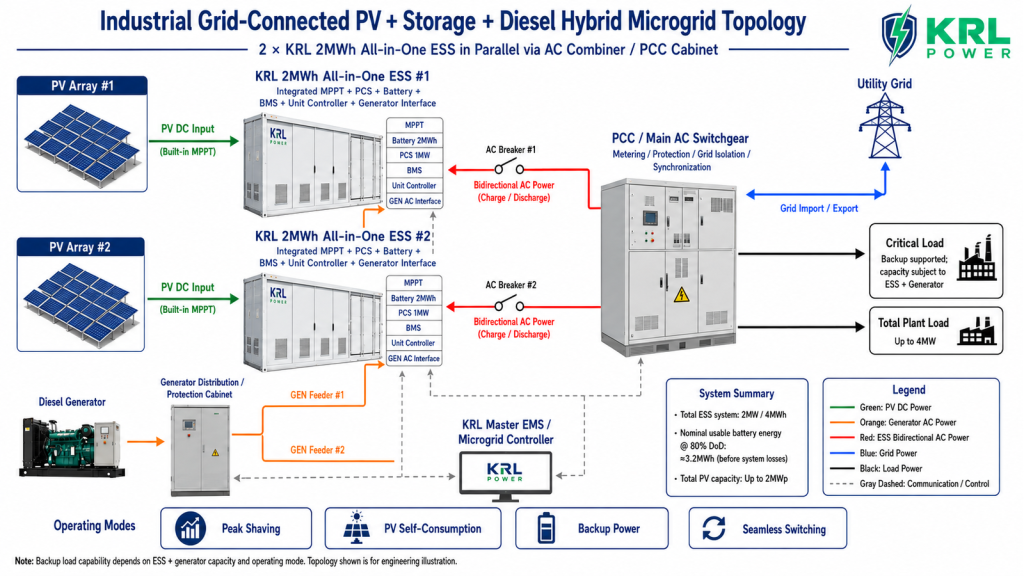
The electrical architecture should clearly show two independent ESS units rather than one artificial 4MWh container. Each storage unit has its own battery, PCS, BMS, MPPT and unit controller. Their PCS AC outputs connect through separate breakers to the common PCC/main AC switchgear.
- PV Array #1 → KRL ESS #1 built-in MPPT: DC-coupled PV input.
- PV Array #2 → KRL ESS #2 built-in MPPT: independent DC-coupled PV input.
- Diesel Generator → Generator Distribution & Protection: the generator supply is protected and distributed to the approved GEN AC interfaces.
- KRL ESS #1 ⇄ AC Breaker #1 ⇄ PCC: bidirectional charge/discharge branch.
- KRL ESS #2 ⇄ AC Breaker #2 ⇄ PCC: second bidirectional branch operating in parallel.
- Utility Grid ⇄ PCC: import/export behavior is controlled according to utility requirements.
- PCC → Factory Loads: main AC distribution point for the plant.
- KRL Master EMS / Microgrid Controller: coordinates both storage units, PCC measurements, generator logic, power limits and operating modes.
Why the Grid Connects to the PCC, Not Directly to One ESS
The utility grid, factory loads and both ESS branches meet at the PCC/main switchgear. This is the correct location for common metering, protection, grid isolation, synchronization, breaker control and import/export management. The two batteries should not be chained together on the DC side, and the grid should not bypass the PCC to feed only one storage unit.
Why the Diesel Generator Uses Protected GEN Feeders
The diesel generator is a long-duration backup source, but it should not be shown as an uncontrolled cable connected into two storage units. The generator passes through a distribution/protection section and then to the approved GEN AC interfaces. Final breaker ratings, synchronization logic, generator controller protocol and multi-ESS generator coordination must be confirmed during project engineering.
How the Egypt Factory Microgrid Operates in Normal and Outage Conditions
Daytime: Use Solar First and Store Excess Energy
During normal daytime operation, solar generation should serve factory loads according to the agreed control strategy. Available excess PV can charge the batteries, increasing solar self-consumption and reducing the amount of electricity imported from the utility. The EMS should keep enough SOC reserve for the customer's backup requirement rather than simply maximizing daily battery cycling.
Peak Demand: Use Both PCS Units to Limit Grid Import
If factory demand reaches 3.5MW while the operator wants to limit utility import to 2MW, the two ESS units can theoretically supply the remaining 1.5MW within their 2MW combined PCS capability. The financial benefit depends on the customer's real tariff, maximum-demand charging method and operating schedule, so KRL should model savings from interval data instead of promising a generic percentage.
Grid Failure: Isolate the Utility and Keep Critical Loads Running
When the grid fails, the PCC protection system must isolate the internal microgrid from the failed utility. The ESS then supports the approved critical-load bus according to the commissioned off-grid/grid-forming strategy. The customer should not interpret a 4MW plant rating as a promise that the 2MW PCS platform can carry the entire factory during an outage.

Long Outage: Battery and Diesel Work Together
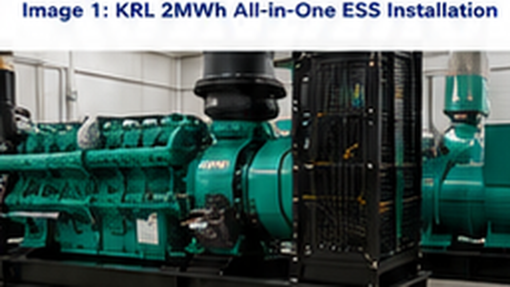
For an eight-hour or longer outage, diesel support can dramatically reduce the amount of battery energy that must be purchased purely for rare long-duration events. The ESS handles fast transfer, PV shifting, power smoothing, generator start bridging and short-duration high-power support. The generator then supplies part of the prolonged load and can support battery SOC when solar generation is insufficient.
How to Meet the Customer's Eight-Hour Backup Target
Option A: Keep 2MW/4MWh and Back Up Only Essential Loads
If the verified eight-hour critical load is in the 300–350kW range, the 4MWh platform may be close to an appropriate battery-only solution after system losses, reserve SOC, ageing and thermal conditions are incorporated. This can be the lowest-CAPEX path when only selected production and safety loads need continuity.
Option B: Use 2MW/4MWh ESS Plus Diesel for Long-Duration Backup
For many factories, this is the stronger commercial solution. The battery provides immediate continuity and daily energy-management value, while the generator covers extended outages. The customer avoids purchasing very large MWh capacity solely for occasional long blackouts while still gaining PV utilization, peak shaving and fast backup from the ESS.
Option C: Expand Battery Capacity for Battery-Only Eight-Hour Operation
If the customer requires eight hours without generator contribution, battery energy must be increased according to the verified critical-load kW. For example, 2MW of critical load for eight hours requires about 16MWh usable energy. At 80% DoD, nominal battery energy is already about 20MWh before conversion losses, auxiliaries, ageing and design reserve.
| Backup strategy | Best fit | Main commercial trade-off |
|---|---|---|
| 2MW/4MWh battery-only for selected loads | Critical load roughly compatible with the available energy | Lowest first-stage battery CAPEX but requires strict load prioritization |
| 2MW/4MWh ESS + diesel | Long outages where generator use is acceptable | Strong balance of daily savings, fast backup and long-duration resilience |
| Larger battery-only system | Customer requires long autonomy without diesel | Higher CAPEX and larger footprint but lower generator dependence |
Egypt Site Engineering, Expansion Plan and Final RFQ Inputs
Why Liquid Cooling Matters in Egypt
Large industrial battery systems must keep cell temperatures consistent. KRL's 2MWh platform uses liquid-cooled battery thermal management. For an Alexandria installation, detailed design should also consider summer ambient temperature, direct solar exposure, dust, cable derating, drainage, service clearances and possible salt-air corrosion near the Mediterranean coast.
- 🌡️ Thermal design: verify worst-case ambient temperature and any project derating.
- 🌬️ Dust and ventilation: define maintenance intervals and equipment clearances.
- 🌊 Coastal environment: evaluate corrosion protection if the site is exposed to salt-laden air.
- 🔌 Cable and switchgear sizing: confirm actual PCC voltage, current and cable distance before final BOM.
- 🔥 Fire and access planning: include fire separation, emergency access and local code requirements.
- 📶 Remote monitoring: select RS485, WiFi or 4G according to the factory's communications infrastructure.
What KRL Needs Before Issuing the Final Technical and Commercial Proposal
The current information is sufficient to recommend the 2MW/4MWh platform as a Phase 1 direction, but not sufficient to guarantee eight-hour autonomy or release a final manufacturing BOM. KRL should request the following items in one technical clarification package.
| RFQ input | What the customer should provide | Why it matters |
|---|---|---|
| Factory SLD | Utility, transformer, PV, generator, bus and load connections | Confirms the real electrical architecture |
| Interval load data | 15-minute or 30-minute load profile | Determines peak-shaving value and actual ESS dispatch |
| Critical-load list | kW/kVA of loads that must survive outages | Determines required PCS power and MWh |
| Existing PV | 500kW inverter model and AC/DC topology | Determines how existing solar should be retained or integrated |
| Future PV | Target modules, strings and inverter/MPPT plan | Confirms the practical path toward 2MWp |
| Generator | Rated kW/kVA, voltage, frequency and controller interface | Confirms long-duration backup integration |
| Grid/PCC | Voltage level, transformer capacity and import/export rules | Determines switchgear, protection and charging limits |
| Site layout | Available area, cable routes and installation photos | Confirms civil work, spacing and cable design |
| Commercial scope | EXW/FOB/CIF preference and Alexandria delivery requirements | Makes quotations technically and commercially comparable |
For related backup design principles, KRL buyers can also review the battery backup for power outages engineering guide.
Engineering Recommendation: Build the Microgrid Around the Critical Load, Not the 4MW Nameplate
For this Alexandria factory, 2 × KRL 1MW/2MWh all-in-one ESS units form a technically logical first-stage platform. The project receives 2MW of combined PCS power, 4MWh of nominal battery energy, modular AC-side parallel operation, direct PV-input capability, fast backup functionality and a generator-assisted path for prolonged outages.
The system is well suited to peak shaving, increased PV self-consumption, backup of correctly selected critical loads and staged microgrid expansion. But KRL should not present 4MWh as an automatic eight-hour backup solution for the entire 4MW plant. The decisive number is the verified critical-load kW during an outage.
Once the factory provides its SLD, interval load data, critical-load schedule, PV configuration and generator information, KRL can determine whether the best investment is 2MW/4MWh, a larger-MWh battery platform, or a 2MW/4MWh ESS + diesel hybrid strategy. That is the difference between selling a battery and engineering a factory energy solution.
Why KRL Power Is a Strong Fit for This Project
KRL Power focuses on commercial and industrial energy storage integration. The company's approach combines long-life battery cells, liquid cooling, intelligent BMS, PCS, EMS, multi-layer protection and modular all-in-one architecture. For an international factory project, that integration is valuable because the customer needs one coordinated power system rather than separate equipment that must be engineered together after delivery.
- 🔋 Modular 2MWh blocks: easy to parallel and expand as the factory's energy requirement becomes clearer.
- ⚡ 1MW PCS per unit: strong power headroom for peak shaving and critical-load support.
- ☀️ Integrated MPPT: direct path for new PV within the approved input limits.
- 🧠 Master EMS + unit controllers: coordinated dispatch, SOC balancing and microgrid operating logic.
- 🌡️ Liquid cooling: supports more consistent battery thermal management in demanding industrial environments.
- 🛡️ Integrated safety architecture: BMS supervision, fire protection and project-level electrical protection.
- 📈 Scalable investment: the customer can begin with 4MWh and expand after real operating data confirms the business case.
FAQ
Can a 2MW/4MWh ESS provide eight hours of backup to a 4MW factory?
No, not if the full factory continuously consumes 4MW. A 4MW load running for eight hours requires about 32MWh of load energy before losses, while the two recommended PCS units provide 2MW combined output. The project must be sized from the critical backup load rather than the site's maximum grid connection.
How much load can a 4MWh battery support for approximately eight hours?
At an 80% preliminary DoD assumption, 4MWh nominal battery energy gives about 3.2MWh of battery-side usable energy before system losses. The theoretical eight-hour average is 400kW, but a real design should be lower because PCS losses, auxiliaries, reserve SOC, ageing and site conditions must be included.
Why use two KRL 2MWh units instead of one 4MWh block?
Two independent 1MW/2MWh units provide 2MW/4MWh combined capacity while supporting AC-side parallel operation, unit-level protection, modular maintenance, coordinated power sharing, staged PV integration and future expansion.
Can the customer's existing 500kW solar PV system be retained?
Potentially yes. KRL should first review the existing PV inverter model and single-line diagram. If the existing 500kW system is already AC-coupled and operating correctly, it may be more practical to retain it and integrate the new storage system at the site AC bus rather than rebuilding working PV equipment.
Can the future 2MWp solar array connect directly to the two KRL 2MWh systems?
The current 2MWh KRL configuration provides up to 960kW PV input per unit, or about 1.92MW published combined direct PV-input capability for two units. The final 2MWp design therefore requires confirmation of array sizing, permitted DC oversizing or a hybrid AC/DC PV architecture.
Does each KRL 2MWh unit contain its own PCS?
Yes. The current project configuration uses a 1MW PCS per 2MWh unit. Two correctly paralleled units therefore provide approximately 2MW combined PCS capability.
Why do both ESS units connect through a PCC cabinet?
The PCC is the common AC coupling point for ESS #1, ESS #2, the utility grid and factory loads. It also provides the correct location for branch breakers, metering, protection, grid isolation, synchronization and import/export control.
How does the diesel generator work with the two ESS units?
The proposed architecture routes the generator through generator distribution and protection before the approved GEN AC interfaces. The Master EMS coordinates generator start/stop, battery SOC, factory load and operating mode. Final generator breaker sizing, controller protocol and multi-unit synchronization must be confirmed during project engineering.
Can the system keep the entire 4MW factory running when the grid fails?
Not from the battery system alone because the two PCS units provide 2MW combined output. The plant should separate critical and non-critical loads. If the customer wants more than 2MW of islanded power or eight-hour operation, generator contribution and/or additional ESS power and energy must be engineered.
Is the KRL 2MWh system suitable for outdoor installation in Egypt?
The current product direction uses liquid-cooled battery thermal management and an IP65 battery enclosure. Final site design should still verify maximum ambient temperature, direct sun, dust, coastal corrosion exposure, drainage, cable derating, maintenance clearance and fire access.
Can the system be expanded beyond 4MWh later?
Yes. Modular scalability is one of the main reasons to use independent 2MWh blocks. Additional ESS units can be evaluated later according to the factory's verified backup requirement, load growth, PV expansion and PCC capacity.
What information should the buyer send KRL Power for a final quotation?
Send the factory SLD, 15- or 30-minute load profile, critical-load list, existing PV inverter data, future PV plan, generator specifications, grid/PCC voltage, transformer rating, import/export requirements, installation layout, delivery destination and required backup duration.
