

Prevent reverse power tripping when pairing BESS with diesel generators by keeping surplus generation away from the genset. The battery must have verified charging headroom; the PV inverters must reduce real power when that headroom runs out; and ANSI 32 protection must remain active. KRL Power offers B261L 125 kW / 261 kWh kwaye B522L 250 kW / 522 kWh cabinets for different power classes. Their actual backfeed-control response has to be proved on the specified genset.
A crusher trips during production. Four hundred kilowatts of factory demand vanish. PV output continues; the diesel governor cannot shed mechanical input immediately. Then the generator's positive-kW reading crosses toward zero. Another breaker trip means another shift of lost production and another argument over whose controller was supposed to act.
An extra 100 kWh of battery capacity cannot rescue an undersized charging converter. The purchase decision rests on three measurable things: how fast the PCS can accept power, how quickly the PV plant can back down, and what the installed ANSI 32 element will tolerate. KRL's 125 kW, 250 kW and plant-class ESS comparison establishes a product shortlist. A witnessed load-rejection response determines whether that shortlist is viable.
What a Sudden Load Drop Does to Generator Power
ANSI 32 measures real-power reversal
During normal operation, the alternator exports positive kW. When a large motor disconnects, the engine is still delivering mechanical power. A surplus on the AC bus can reverse the alternator's real-power flow, pulling the machine into motoring. ANSI 32 detects that condition and initiates the protection action configured for the generator.
Read real kW at the generator terminals, including its sign. An apparent reverse-current indication is insufficient. A reversed CT, incorrect VT phase reference or inverted meter convention can make an otherwise healthy installation look as though it is backfeeding. Check wiring, measured kW and the relay event record before anybody edits a setting.
Do not bypass ANSI 32 to make the trip disappear. That removes an essential protection function while the power-flow fault remains.
A three-second relay setting does not tell the whole story
A Cummins PowerCommand technical specification, for example, gives an adjustable reverse-power threshold of 5–20% of standby rated kW kunye ne 1–15-second delay, with defaults of 10% and 3 seconds. This is a manufacturer-specific reference, hayi a setting to copy into every diesel microgrid. The installed relay, engine limits, protection study and IEEE C37.102 guidance govern the actual design.
A reverse-kW event can begin immediately after load rejection without producing an instantaneous ANSI 32 trip. Pickup, filtering and timing logic still apply. Some Cummins controllers use integrating reverse-power timing: several brief negative-kW excursions can build toward shutdown. Severe frequency or voltage deviations may trip another protective element first. Record all of them when diagnosing the event.
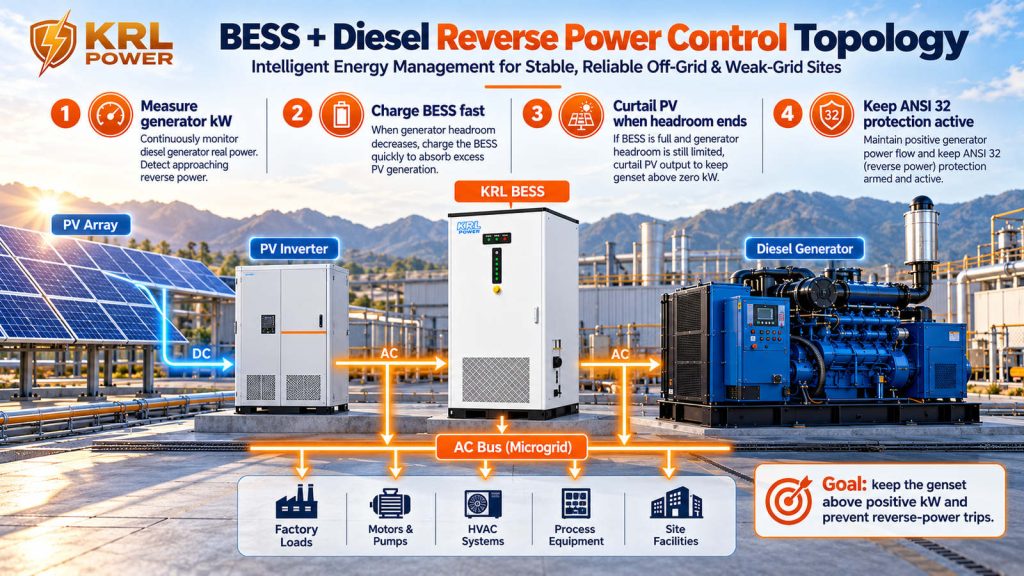
The trouble usually starts with a stopped motor or rising PV
A crusher, compressor or pump group trips offline. Load falls, but diesel mechanical input and PV generation cannot follow at the same pace. If the BESS continues discharging, it adds another source of unwanted power.
A cloud edge increases PV output while factory demand holds steady or falls. Generator export shrinks. An almost-full battery and a slow inverter power-limit command leave little room for correction.
These are power-control events. The relevant procurement evidence is the permitted charging kW at the operating SOC, the measured response time and the relay's actual pickup characteristic. More battery kWh, by itself, changes none of those limits.
The Shortcuts That Keep Reverse-Power Trips Coming
Permanent PV derating buys margin at a price
A permanently low PV setpoint may suppress reverse power at light factory load. At higher demand, that same limit throws away solar generation the site could have consumed. An effective PV cap tracks factory demand, approved minimum generator output and live battery charge headroom. A constant cap may reduce trips; it also hides the missing control sequence.
Kwezika-R.L. solar-storage-diesel cabinet architecture integrates the PCS, battery and specified PV functions with a diesel interface. That can simplify the cabinet supply boundary. An existing AC-coupled solar plant remains a separate control responsibility; its inverter must receive and obey the right curtailment command in the witnessed test.
Minimum generator loading must come from the engine data
The generator's minimum forward-kW target must come from the engine manufacturer's permitted operating range and the site protection study. The governor behavior and duration of low-load operation also matter. Picking 25%, 30% or 40% from an online article is not engineering.
Prolonged low-load operation can produce wet-stacking problems on susceptible engines; holding a machine at 40% is not inherently the cause. The waste comes from burning fuel while solar is curtailed because the control boundary has never been settled. KRL's diesel-cost analysis covers that financial tradeoff. Here, the first obligation is to keep the generator inside its approved operating envelope.
Supervisory dispatch cannot carry the entire transient
A scheduler that manages generator hours and SOC may work perfectly at steady load and still miss the first part of a crusher trip. The initial correction must come from demonstrated PCS and PV control functions; supervisory dispatch handles the recovered operating point.
Time the whole path under load: generator kW sensing → data update → control decision → PCS charging change → PV reduction → recovered generator kW. Quoted scan time is not end-to-end response. Modbus, RS485 and hardwired contacts can all be components of a working design, depending on the devices and their failure states. Nor does a DSE or ComAp datasheet prove compatibility with the exact KRL controller and firmware being ordered.
Prevent Generator Backfeed With a Fast PCS–PV Control Path
The PCS must have charging headroom ready
In a conventional diesel-led island, the genset establishes AC voltage and frequency. The PCS must be commissioned for parallel operation with that source. When factory load disappears, the battery should first stop any unnecessary discharge and then take in as much power as its verified charge limit permits.
Require the PCS supplier to demonstrate the relevant operating mode, power reversal, charging ramp and interaction with the diesel governor. VSG, droop and grid-forming are control descriptions, not guaranteed charging response times. A rise in bus voltage is also not a substitute for measuring generator active kW; real-power imbalance primarily affects frequency and machine dynamics.
Reserve charging capability while the system is still running normally. High SOC, battery temperature and operating limits can reduce charging power below the PCS's advertised AC output rating. A procurement schedule must state the limit at the actual test condition.
PV must back down when the battery cannot take more
Battery charging cannot be the only escape route. Once the permitted charge limit is reached, PV real-power output must decrease or another approved sink/source-control action must cover the mismatch. Capture inverter command receipt, measured power reduction and the response to stale or lost telemetry. Adjusting reactive power does not remove a surplus of real kW.
A local fast-control function may have to act before the supervisory EMS updates its dispatch. The test must show a stable recovery and controlled restoration of PV once the diesel export and battery charge headroom are back inside their limits.
Protection gets the final word
The power-management controller should act while the genset is still exporting positive kW, with enough margin for metering error and actuator delay. Keep ANSI 32 independent and functional. The protection engineer owns pickup, the timing characteristic, motoring limits and the generator breaker trip path.
SMA and Schneider describe generator power-management schemes involving BESS charging and PV limiting. These demonstrate established engineering approaches; they are not evidence for an unverified KRL controller response specification.
After a 400 kW Load Drop, How Much Can the BESS Actually Absorb?
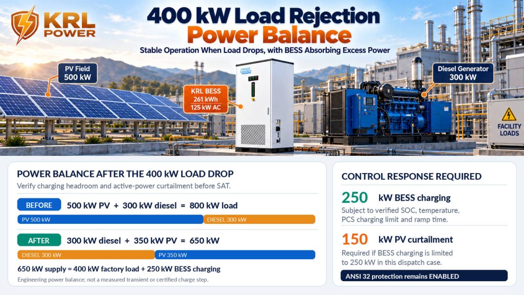
The following numbers are an engineering power-balance example, not a KRL factory test or client project. A factory operates a 1,000 kW-rated diesel generator, 500 kW of existing AC-coupled PV kwaye 800 kW of demand. Losses are omitted for this initial calculation.
| Initial operating condition | Amandla asebenzayo |
|---|---|
| Factory demand | 800 kW |
| AC-coupled PV | 500 kW |
| Ijenereyitha yedizili | +300 kW |
| BESS charging/discharging | 0 kW |
Now the crusher trips and 400 kW of demand disappears. The site load falls to 400 kW, but PV is still producing 500 kW. With no BESS or PV correction, the steady algebraic balance would call for −100 kW at the generator. That negative value flags a serious backfeed risk; it does hayi predict the measured transient waveform, which depends on the machine, governor and protection response.
Suppose this project has an approved generator operating target of +300 kW. Keeping PV at 500 kW after the trip requires the BESS to charge at:
300 kW generator + 500 kW PV − 400 kW factory load = 400 kW BESS charging.
B261L is rated 125 kW AC and B522L 250 kW AC. Those output ratings do not certify a 400 kW charging step, and the published under-10 ms on/off-grid transfer figure measures an entirely different function. A single B522L must not be sold as a proven 400 kW absorption solution.
If a 250 kW charging capability has been verified at that SOC, temperature and operating mode, PV must fall to 350 kW. That means 150 kW of curtailment while the generator remains at the assumed +300 kW target:
300 kW generator + 350 kW PV = 400 kW factory load + 250 kW BESS charging.
Kwi zero available battery charging, PV would have to fall to I-100 kW to maintain that assumed generator target, unless another approved controllable load or operating change is available. The arithmetic gives a target; only a timed load-step test can show whether the controller reaches it before the relevant protective element acts.
The energy involved in a 400 kW imbalance over three seconds is just 0.33 kWh. Capacity is not the bottleneck. Charging kW, reversal speed, PV curtailment and protection coordination are.
For a genuine requirement above the 250 kW class, examine KRL's B2M6L plant-class equipment, which lists 750 kW / 1.5 MWh kwaye 1,000 kW / 2 MWh AC output variants with published integrated PV inputs of 720 kW kwaye 960 kW. Confirm actual AC charging power, response, current, operating mode and protection. The existing AC-coupled PV plant in this example cannot be treated as approved merely because the cabinet has a DC MPPT rating.
Match the KRL Cabinet to the Disturbance, Not Just the Battery Size
A 522 kWh nameplate cannot cover a 400 kW reverse-power event unless the converter and controls can respond. Size the charging and curtailment duties before choosing the energy capacity. KRL Power provides 125 kW, 250 kW and plant-class hardware; the EPC can shortlist an appropriate platform without pretending the battery alone solves protection.

| KRL model | Published equipment boundary | Where to begin the review |
|---|---|---|
| B261L | 125 kW / 261 kWh; maximum AC current 189 A; PV input up to 120 kW; diesel port | Smaller industrial feeders whose proven charge and PV-control response fits the disturbance |
| B522L | 250 kW / 522 kWh; maximum AC current 375 A; PV input up to 240 kW; diesel port | Larger production blocks needing the 250 kW equipment class |
| B2M6L | 750 kW / 1.5 MWh or 1,000 kW / 2 MWh; PV input 720 kW / 960 kW; diesel port | Plant-class studies where the power duty exceeds a single C&I cabinet |
KRL B522L puts PCS, BMS, EMS, PV MPPT and a diesel-generator interface in a single cabinet. For an EPC, that consolidates much of the cabinet-level equipment scope and gives the interface schedule a clearer starting point. The generator's external protection, breaker coordination, synchronization and PCS response tests remain separate engineering obligations.
Lead with B261L for a verified 125 kW-class feeder; B522L is the primary KRL option at 250 kW. If the duty exceeds a single cabinet, examine a specified B2M6L configuration. Each choice still requires measured charging limits and a witnessed transient response. The South Africa ESS equipment-selection guide explains why AC current and power limits can rule out equipment long before its kWh become relevant.
Ask for the diesel-controller details behind the port
The published KRL model tables specify diesel-generator ports and RS485/Wi-Fi connectivity. They do not identify a separately certified millisecond reverse-power controller or support blanket plug-and-play claims for DSE, ComAp, DEIF and Woodward families.
Before approving the purchase, obtain the controller model and firmware, meter/CT location, protocol registers, hardwired I/O, breaker permissions, failure states and witnessed response data. The Bangladesh textile microgrid example gives broader system context. The narrower question here is whether the proposed cabinet and its documented controls can handle the project's worst credible reverse-kW event.
The review should identify an appropriate power class, the missing controller/interface evidence and the load-step tests the EPC must specify.
The Control Schedule Must Say Who Owns Each Command
The generator supplier says the PV inverter caused the trip. The solar supplier points to the battery. The EPC discovers that no contract assigned the first moments of the load-rejection response. Put that responsibility on the signed single-line diagram and control schedule before commissioning.
| Into yesivumelwano | The EPC must specify | Risk when it is missing |
|---|---|---|
| Generator active-kW sensing | CT/VT position, ratio, polarity, signal sign, update interval | False or missed reverse-power indication |
| ANSI 32 protection | Relay model, pickup, delay or integrating logic, motoring allowance, trip path | Poor selectivity or unprotected prime mover |
| Diesel operating floor | Approved minimum forward kW, governor/AVR settings, permitted duty | Engine operates outside approved load envelope |
| PCS active-power control | Charge limits at SOC/ambient, measured ramp, local control authority | BESS cannot accept the expected load step |
| PV active-power limiting | Compatible inverter command, response, fail-safe state | PV continues exporting after headroom disappears |
| Control hierarchy | Fast local action, supervisory dispatch, breaker authority, interlocks | Conflicting commands during the same event |
| Communications failure | Stale-meter alarm, timeout, safe PV/BESS state, reset procedure | Frozen or incorrect generator measurement drives PCS |
| Multiple gensets | Individual-unit kW and reverse-power logic, load-sharing roles | One engine motors despite positive combined plant kW |
A DSE or ComAp controller may be included, provided the specific interface is validated. Assign four owners: the device measuring generator kW, the device commanding battery charging, the device reducing PV output and the protection device that trips each breaker. KRL's Nigeria factory solar–diesel integration guide covers wider dispatch. The scope here is the ANSI 32 protection boundary.
Make the Load-Rejection Test a Condition of Acceptance
A successful startup test tells the EPC almost nothing about the next major load rejection. Put largest credible motor loss, PV ramp, high-SOC charging limit and controller-failure response in the FAT/SAT acceptance scope. Keep the generator protection enabled and use an engineer-approved safe test procedure.
| Witness event | Record and assess |
|---|---|
| Agreed large-load rejection | Peak negative generator kW, pulse duration, PCS charge response, PV reduction and frequency |
| PV ramp-up | Whether generator output respects its approved positive-kW boundary |
| High-SOC battery | Battery charge ceiling and the controller’s PV fallback |
| PCS derating or unavailable charging | Whether the controller detects reduced headroom and takes corrective action |
| Meter sign error / telemetry loss | Stale-value timeout, known-positive-kW polarity test, safe-state response |
| Repeated short negative-kW pulses | Whether an integrating ANSI 32 element accumulates repeated excursions |
| Generator governor or control fault | Correct control ownership, protection interlocks and breaker behavior |
| Multiple gensets, if installed | Individual reverse-kW trace and load-sharing stability |
| Black start or transfer, if contracted | Operating mode ownership, synchronization and breaker interlocks |
Collect five synchronized traces at minimum: generator active kW, PV active kW, BESS active kW, bus frequency and ANSI 32 pickup/trip status. Archive SOC, permitted charging kW, event timestamps and breaker states alongside them. Where the installed relay integrates reverse-power exposure, check repeated short pulses, not just the single longest excursion.
The responsible protection engineer defines safe test steps and pass/fail limits. Document firmware, settings and witnessed results. A test that passes only after ANSI 32 is disabled has not proven reverse-power protection.
Stop Paying for the Same Generator Trip Twice
A reverse-power trip after handover is a control failure the owner will remember longer than the cabinet brochure. Measure generator kW, reserve actual charging headroom, verify PV limiting and retain independent ANSI 32 protection. Those four actions determine whether the next load loss becomes a controlled event or a production stoppage.
Specify KRL B261L for a verified 125 kW-class duty, B522L for an engineered 250 kW-class feeder and an exact B2M6L variant for plant-scale power. Then make the PCS, PV inverter and generator-controller suppliers witness the same load-rejection test with protection enabled.
Reject an undersized PCS before the purchase order. Reject an untested control sequence before the site goes live.
A useful outcome is a power-class shortlist, agreed controller responsibilities and a test plan the EPC can carry into technical approval.