 Yiya kumxholo

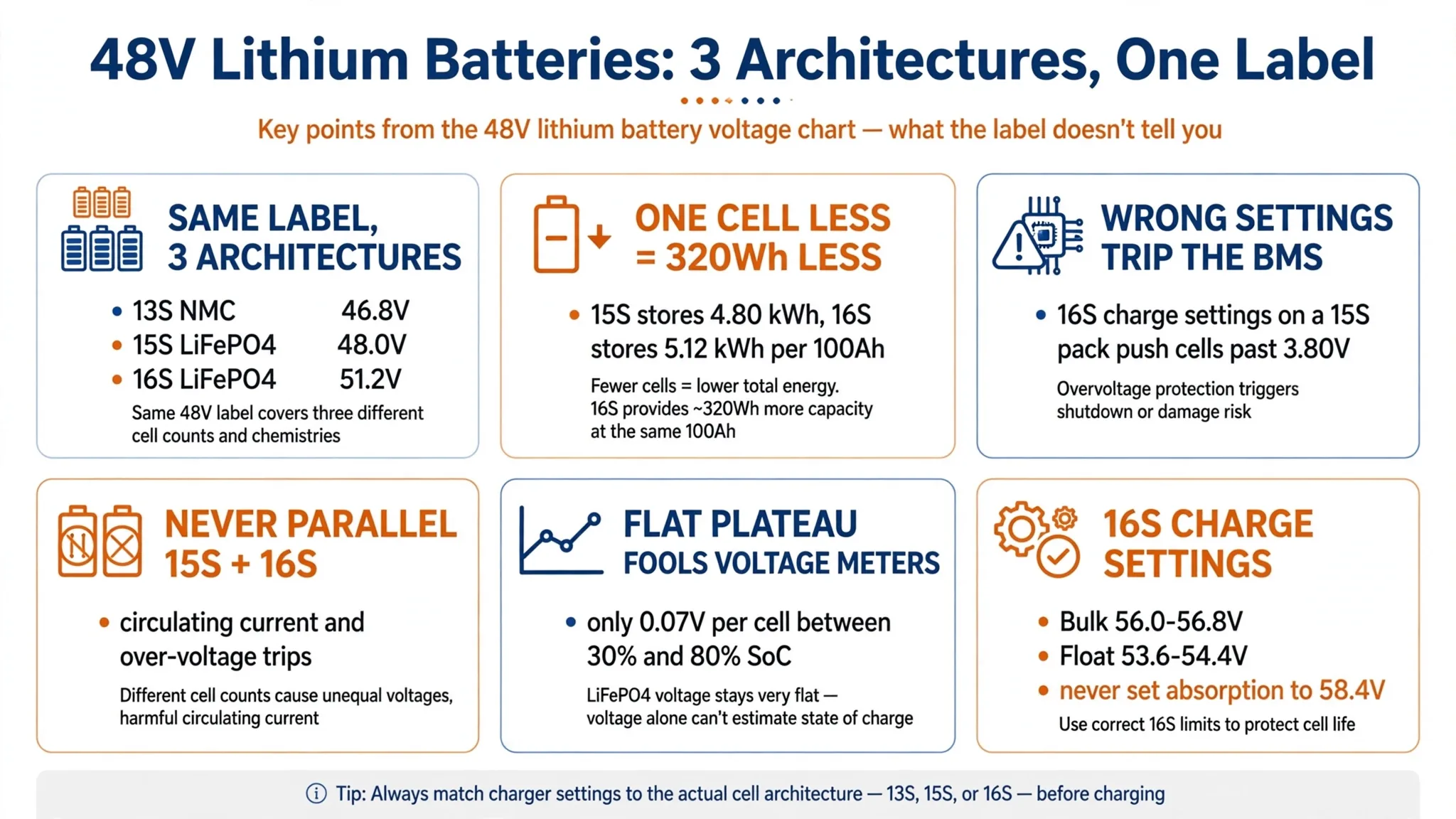
Suppliers sell three distinct battery architectures under the label "48V 100Ah lithium battery" in the KRL 48V lithium battery range: **13S NMC** (46.8V / 48.1V nominal), **15S LiFePO4** (48.0V nominal, 4.80 kWh), and **16S LiFePO4** (51.2V nominal, 5.12 kWh).
Treating those three packs as interchangeable causes two expensive problems on site and in procurement:
- Capacity shortfall at purchase: A 15S 100Ah LiFePO4 pack contains one fewer cell than a standard 16S 100Ah pack. That removes 320 Wh of storage (6.25% less usable energy), hidden behind a quote that looks 5% to 7% cheaper per pack.
- Midday BMS over-voltage trips on site: Charging a 15S pack using 16S voltage settings (57.6V–58.4V) drives the cells past 3.80V per cell at solar noon, forcing the battery management system (BMS) into High-Voltage Disconnect (OVP). Charging a 16S pack on 15S settings leaves it undercharged and unbalances the cell string.
Below are the electrical comparison tables, the 0%–100% state-of-charge (SOC) resting voltage chart, the procurement breakdown between 15S and 16S, and field-tested charger settings for Deye, Victron, Growatt and Luxpower inverters.
1. 48V Lithium Battery Voltage Charts: 13S NMC vs. 15S & 16S LiFePO4
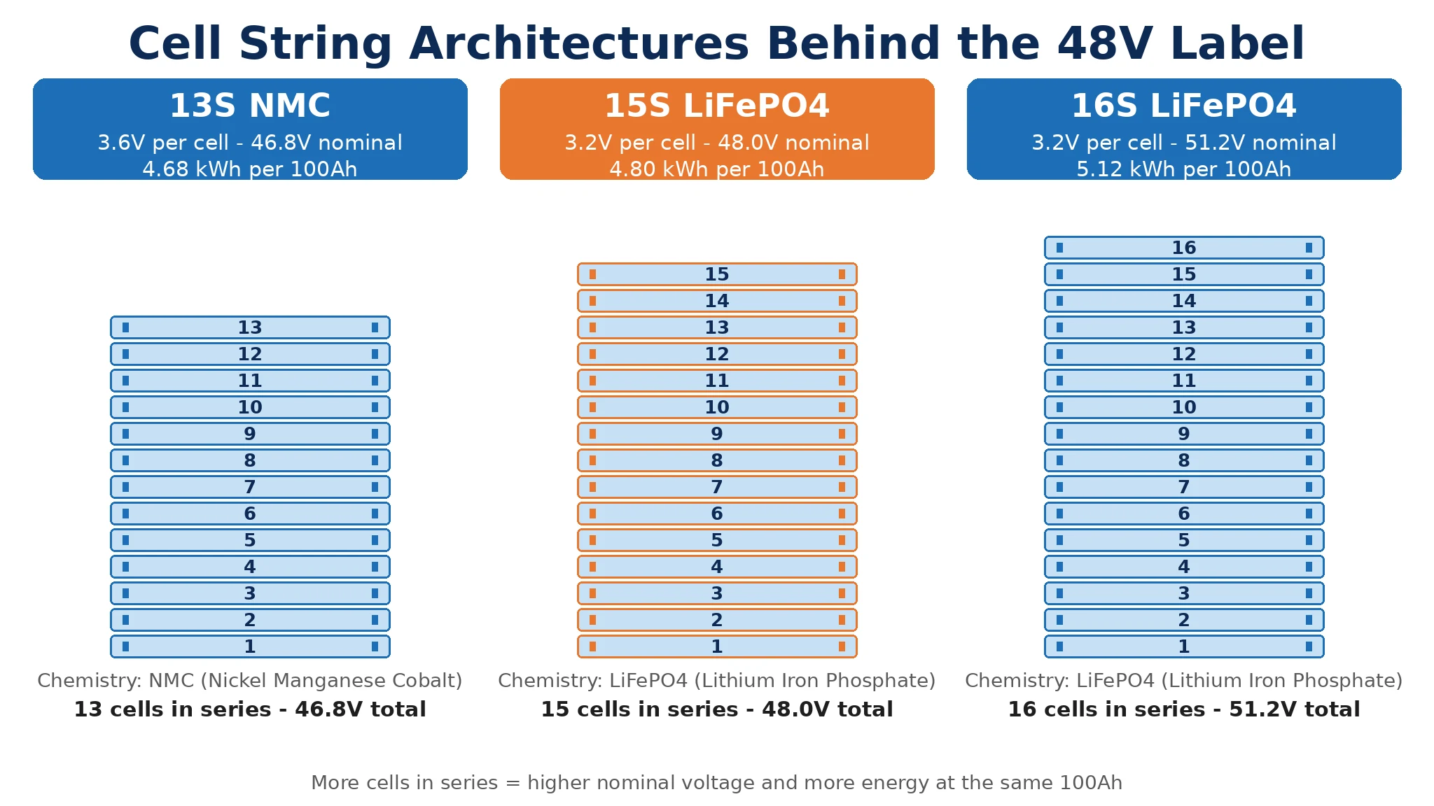
Table 1: Electrical architecture and operating parameters (100Ah reference pack)
| Ipharamitha | 13S NMC (Nickel Manganese Cobalt) | 15S LiFePO4 (Telecom / Legacy 48V) | 16S LiFePO4 (Standard Solar / C&I 51.2V) |
|---|---|---|---|
| Series cell count | 13 cells in series | 15 cells in series | 16 cells in series |
| Nominal cell voltage | 3.60V / 3.70V | 3.20V | 3.20V |
| Nominal pack voltage | 46.80V / 48.10V | 48.00V | 51.20V |
| Rated energy (per 100Ah) | 4,680 Wh – 4,810 Wh | 4,800 Wh (4.80 kWh) | 5,120 Wh (5.12 kWh, +6.67% vs 15S) |
| 100% theoretical max charge (BMS OVP limit) | 54.60V (4.20V/cell) | 54.75V (3.65V/cell) | 58.40V (3.65V/cell) |
| Recommended bulk / absorption voltage | 53.30V – 53.95V (4.10–4.15V/cell) | 52.50V – 53.25V (3.50–3.55V/cell) | 56.00V – 56.80V (3.50–3.55V/cell) |
| Recommended float voltage | Float not recommended (≤50.70V if required) | 50.25V – 51.00V (3.35–3.40V/cell) | 53.60V – 54.40V (3.35–3.40V/cell) |
| Recommended inverter low-DC cut-off | 39.00V – 40.30V (3.00–3.10V/cell) | 42.00V – 43.50V (2.80–2.90V/cell) | 44.80V – 46.40V (2.80–2.90V/cell) |
| 0% BMS under-voltage protection (UVP) | 36.40V – 39.00V (2.80–3.00V/cell) | 37.50V – 40.50V (2.50–2.70V/cell) | 40.00V – 43.20V (2.50–2.70V/cell) |
| Typical cycle life (80% DoD, 25°C) | 800 – 1,500 cycles | 4,000 – 6,000 cycles | 6,000 – 8,000+ cycles |
| Thermal runaway onset temperature | ~200°C – 210°C | >480°C – 500°C | >480°C – 500°C |
| Primary applications | Light EVs, golf carts, mobility | -48V telecom base stations, Pylontech US series | Residential & C&I solar storage, rack/wall ESS |
Table 2: 0% to 100% SOC resting open-circuit voltage chart (at 25°C after ≥1 hour rest)
*Note on measurement:* The values below represent resting open-circuit voltage (OCV) after charging or discharging has stopped for at least 60 minutes. During active charging, terminal voltage on a LiFePO4 pack reads 1.5V to 4.0V higher than the resting figures below.
| State of Charge (SOC) | 13S NMC Pack (Cell V) | 15S LiFePO4 48V Pack (Cell V) | 16S LiFePO4 51.2V Pack (Cell V) | Operating Status |
|---|---|---|---|---|
| 100% (Active Charging Peak) | 54.60V (4.20V) | 54.00V – 54.75V (3.60–3.65V) | 57.60V – 58.40V (3.60–3.65V) | Charger saturation / cell balancing |
| 100% (Resting OCV) | 54.34V (4.18V) | 51.00V (3.40V) | 54.40V (3.40V) | Full charge, surface charge settled |
| 90% | 52.78V (4.06V) | 50.25V (3.35V) | 53.60V (3.35V) | Upper knee transition |
| 80% | 51.48V (3.96V) | 49.95V (3.33V) | 53.28V (3.33V) | Flat plateau begins (LiFePO4) |
| 70% | 50.31V (3.87V) | 49.80V (3.32V) | 53.12V (3.32V) | Flat plateau |
| 60% | 49.27V (3.79V) | 49.50V (3.30V) | 52.80V (3.30V) | Flat plateau |
| 50% | 48.36V (3.72V) | 49.35V (3.29V) | 52.64V (3.29V) | Mid-capacity plateau |
| 40% | 47.58V (3.66V) | 49.20V (3.28V) | 52.48V (3.28V) | Flat plateau |
| 30% | 46.80V (3.60V) | 48.90V (3.26V) | 52.16V (3.26V) | Flat plateau ends; voltage starts dropping |
| 20% | 45.89V (3.53V) | 48.30V (3.22V) | 51.52V (3.22V) | Lower knee; trigger generator / grid recharge |
| 10% | 44.46V (3.42V) | 46.50V (3.10V) | 49.60V (3.10V) | Recommended inverter low-DC cut-off zone |
| 0% (BMS Cut-off) | 36.40V – 39.00V (2.80–3.00V) | 37.50V – 40.50V (2.50–2.70V) | 40.00V – 43.20V (2.50–2.70V) | Cell depletion; BMS opens discharge MOSFETs |
**Why voltage-only SOC meters fail on LiFePO4 between 30% and 80%:** Across the 50% capacity band from 30% SOC to 80% SOC, a LiFePO4 cell's resting voltage changes by 0.07V (from 3.26V to 3.33V), which is 1.12V across a 16S pack. Temperature shifts, cable drop or a small load mask a 1V difference. Inverters running in "Lead-Acid / Voltage Mode" cannot estimate LiFePO4 state of charge in this middle region. Reliable SOC tracking requires a BMS with a calibrated shunt (coulomb counter) talking to the inverter over closed-loop CAN or RS485, with periodic full charges to 3.50V–3.55V/cell to reset the 100% counter.
2. 15S (48.0V) vs. 16S (51.2V) LiFePO4: Telecom Legacy vs. Solar Cost-Cutting
Telecom origins of the 15S LiFePO4 architecture
The 15S LiFePO4 configuration originated in the telecom tower and data-centre market, where KRL BBU and UPS battery solutions must match the site DC bus and rectifier limits. Legacy -48V DC telecom rectifiers were engineered around 24-cell lead-acid strings, whose equalize voltage stayed below 56.0V to 56.4V.
A 16S LiFePO4 pack requires 56.0V to 57.6V for a full charge, which hits the high-voltage alarm threshold on older telecom rectifiers and can trip legacy DC radio equipment. Using 15 cells instead of 16 lowered the maximum charge voltage to 52.5V–54.0V, letting telecom operators drop lithium packs onto existing -48V DC busbars without replacing their rectifiers. Pylontech's early US2000/US3000 residential racks also adopted 15S for backward compatibility.
False economy of 15S packs in modern solar storage
Modern 48V hybrid and off-grid solar inverters (Deye, Victron, Sunsynk, Growatt, Luxpower, Voltronic, SMA, Megarevo) accept a DC battery input up to 60V–64V. Outside telecom rectifier retrofits or expanding an existing 15S bank, there is no technical reason to install 15S in a new solar project.
Unbranded or white-label assembly workshops using standard off-the-shelf lithium battery formats still sell 15S packs as "48V 100Ah solar batteries" because removing the 16th cell cuts the bill of materials by 6%:
- You receive 6.25% less energy per pack: A 15S 100Ah pack stores $48.0\text{V} \times 100\text{Ah} = 4.80\text{ kWh}$. A 16S 100Ah pack stores $51.2\text{V} \times 100\text{Ah} = 5.12\text{ kWh}$. Across a 10-pack commercial rack (48.0 kWh vs. 51.2 kWh), the missing 10 cells equal 3.2 kWh, or two-thirds of a battery module missing from the rack.
- Higher $/kWh despite a lower sticker price: If a supplier quotes a 15S 100Ah pack at $660 and a true 16S 100Ah pack at $700, the 15S pack looks $40 cheaper. Divided by actual energy, the 15S pack costs $137.50/kWh while the 16S pack costs $136.72/kWh, and requires extra cabling and rack space per kWh.
- Higher current and $I^2R$ heat losses for the same kW load: To deliver 5,000 W to an inverter at 50% SOC, a 16S pack at 52.6V draws 95.0 A, whereas a 15S pack at 49.3V draws 101.4 A. That 6.7% increase in current raises $I^2R$ resistive heating in your DC cables, fuses and BMS MOSFETs by ~14%.
Never wire 15S and 16S battery packs in parallel
Installers sometimes try to expand an existing 48V rack by paralleling a new 16S (51.2V) battery onto an older 15S (48.0V) bank, or vice versa:
- Inrush circulating current at connection: A resting 16S pack at 80% SOC sits at ~53.3V, while a 15S pack at 100% SOC sits at ~51.0V. Closing the breaker between them drives tens or hundreds of amps from the 16S pack into the full 15S pack, tripping BMS over-current or over-voltage protection right away.
- Overcharge of the 15S pack and starvation of the 16S pack: At a bus voltage of 53.6V, the 15S pack is at 3.57V/cell (100% full) while the 16S pack is at 3.35V/cell (just beginning absorption). If the inverter charges to 56.0V, the 15S pack disconnects on OVP; if the inverter stops at 53.2V, the 16S pack never reaches top balance and drifts out of calibration.
3. Why 13S NMC Is Being Phased Out of Stationary Solar & BESS
Second-life EV modules and low-cost 48V packs built with 13S NMC (Lithium Nickel Manganese Cobalt) cells, including KRL’s 48V 20Ah 13S lithium-ion pack appear in price-sensitive off-grid markets. NMC offers higher gravimetric energy density (Wh/kg) for electric motorcycles and forklifts, but stationary solar installers and commercial insurers reject it for three engineering reasons:
- Thermal runaway and oxygen release: Layered oxide NMC cathodes begin exothermic decomposition around 200°C–210°C, releasing free oxygen ($O_2$) inside the cell that feeds an internal fire even without external air. Olivine-structure LiFePO4 ($LiFePO_4$) holds its phosphorus-oxygen covalent bond past 480°C–500°C and does not release oxygen during decomposition.
- Cycle life and Levelized Cost of Storage (LCOS): A 13S NMC pack reaches 80% State of Health after 800 to 1,500 daily cycles (2.5 to 4 years of daily solar cycling). A Grade-A 16S LiFePO4 pack delivers 6,000 to 8,000+ cycles (15+ years). Even if an NMC pack costs 20% less upfront, its lifetime cost per delivered kWh is more than triple that of LiFePO4.
- Steep voltage swing under load: A 13S NMC pack swings from 54.6V full down to 36.4V empty, an 18.2V spread that forces inverter DC-DC stages to run at lower efficiency at the bottom of the discharge curve.
4. Field-Tested Inverter Voltage Settings (Zero-OVP Configuration)
Why setting absorption to 3.65V/cell (58.4V) causes nuisance BMS trips
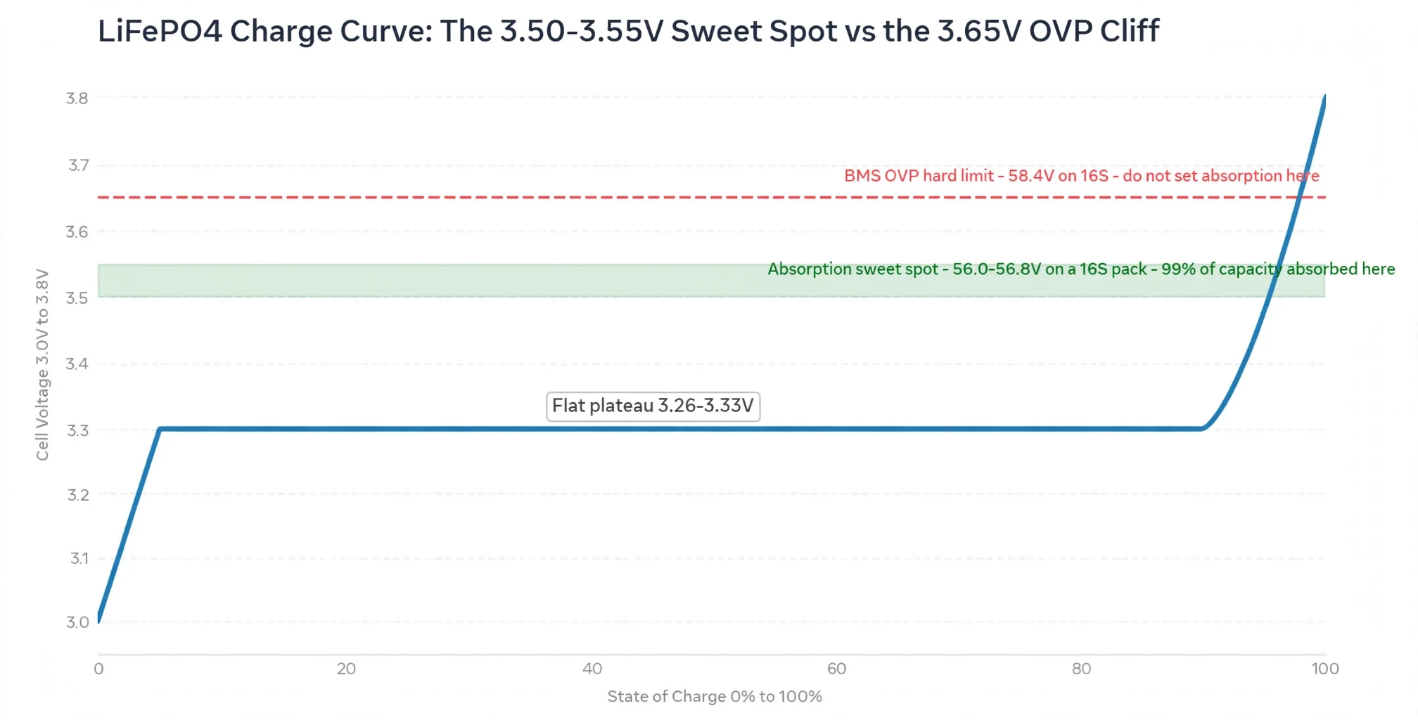
Datasheets list 3.65V/cell (54.75V for 15S; 58.40V for 16S) as the absolute maximum charge cut-off voltage for LiFePO4. Installers who enter 58.4V into their inverter's Bulk/Absorption setting often get called back when the battery trips offline every sunny afternoon.
A LiFePO4 cell absorbs 99%+ of its usable capacity by 3.50V–3.55V. Above 3.50V, the voltage curve shoots upward: a 1% state-of-charge difference between two cells in a 16-cell string can push the fastest cell past 3.65V (triggering single-cell BMS OVP disconnect) while the remaining 15 cells sit at 3.52V.
Charging to 3.50V–3.55V per cell (56.0V–56.8V on 16S; 52.5V–53.25V on 15S) gives the passive or active balancer time to equalize the cells near the top of the knee without hitting the 3.65V hard trip limit.
Recommended manual voltage settings for Deye, Victron, Growatt & Luxpower
Connect the battery BMS to the inverter via CAN bus or RS485 BMS communication whenever the hardware supports it, so the BMS controls charge voltage and current limits. For systems running in User-Defined / Open-Loop Voltage Mode, use these field-proven settings:
| Inverter Parameter | 16S LiFePO4 (51.2V Nominal) | 15S LiFePO4 (48.0V Nominal) | Engineering Rationale |
|---|---|---|---|
| Bulk / Absorption Voltage (CV) | 56.0V – 56.8V (3.50–3.55V/cell) | 52.5V – 53.2V (3.50–3.55V/cell) | Reaches >99% SOC and activates top balancing with a 0.10–0.15V/cell buffer below BMS OVP |
| Absorption Time | 30 – 60 minutes | 30 – 60 minutes | Gives the BMS balancer time to bleed high cells before dropping to float |
| Float Voltage | 53.6V – 54.4V (3.35–3.40V/cell) | 50.3V – 51.0V (3.35–3.40V/cell) | Holds pack above resting OCV so solar powers loads without over-stressing cells |
| Equalization Charging | Disabled (OFF) | Disabled (OFF) | Lead-acid equalization (>60V) trips or damages a lithium BMS |
| Temperature Compensation | 0 mV/°C (Disabled) | 0 mV/°C (Disabled) | Do not apply lead-acid negative temperature compensation to LiFePO4 |
| Back to Grid / Recharge Voltage | 51.2V – 51.8V (~20–25% SOC) | 48.0V – 48.5V (~20–25% SOC) | Leaves a reserve buffer for unexpected outages |
| Low DC Cut-off Voltage | 45.6V – 46.4V (2.85–2.90V/cell) | 42.8V – 43.5V (2.85–2.90V/cell) | Shuts down the inverter before the BMS opens its internal MOSFETs (which would leave the inverter dark and unable to black-start from solar) |
| Max Charge Current | 0.2C – 0.5C (20A–50A per 100Ah) | 0.2C – 0.5C (20A–50A per 100Ah) | Keeps cell core temperatures low and extends cycle life past 6,000 cycles |
5. How KRL Power Builds True 16S (51.2V) & Telecom 15S Systems
At KRL Power, we manufacture, backed by KRL Power’s manufacturing background, both low-voltage rack/wall modules such as KRL LiFePO4 battery solutions and high-voltage commercial energy storage cabinets from traceable Grade-A LFP cells, eliminating the capacity shortcuts found in trading-company packs:
- 100% True 16S (51.2V) architecture for solar storage using KRL 51.2V home energy storage batteries: Every KRL 51.2V 100Ah and 200Ah rack-mount and wall-mount battery uses 16 matched automotive-grade LiFePO4 cells. Factory capacity testing verifies >102% nominal watt-hours before shipment, with individual cell batch QR codes mapped to each cabinet's serial number.
- Dedicated -48V (15S) blade packs for telecom operators: For telecom tower contractors integrating onto legacy -48V DC rectifiers, we produce a dedicated 15S (48.0V) telecom rack series with anti-theft locking, SNMP/RS485 monitoring and rectifier-compatible voltage limits, separated by part number so warehouse teams never mix 15S and 16S units.
- Pre-loaded CAN / RS485 protocols for 30+ inverters: Our smart BMS (with coulomb-counting SOC accuracy within ±3%) ships with selectable protocol profiles for Deye, Victron, Sunsynk, Growatt, Luxpower, Voltronic, GoodWe, SMA, Solis and Megarevo, removing manual voltage guesswork on site.
- Full product scaling from 5.12 kWh to multi-MWh: Distributors can source residential and light-commercial 51.2V modules alongside 125 kW / 261 kWh outdoor C&I liquid- or air-cooled storage cabinets from a single factory supply chain.
6. Get the Workshop Voltage Chart and Inverter Setup Support
Stop losing 6.25% capacity on under-sized 15S quotes or spending service hours clearing midday BMS over-voltage alarms.
- For solar distributors, wholesalers and OEM/ODM partners: Looking for factory-direct pricing on full-capacity 16S (51.2V) Grade-A rack/wall batteries or 125 kW / 261 kWh C&I storage cabinets? Contact KRL Power to request our distributor price list and cell test reports.
- For telecom infrastructure and off-grid project engineers: Need dedicated -48V (15S) telecom rack batteries or custom hybrid microgrid storage? Contact KRL Power for project engineering support.
