
Une usine de soudage nigériane dont la capacité mesurée est de charge totale de 500 kW et trois 150–200 kW production groups needs enough inverter power to carry scheduled production, absorb operating variation and keep the three-phase bus stable. KRL Power’s published B2M6L 1,5 MWh / 750 kW Cette configuration constitue un point de départ plausible pour répondre à cette exigence, car sa puissance nominale dépasse de 250 kW la charge totale indiquée et son énergie nominale correspond à trois heures à une puissance constante de 500 kW.
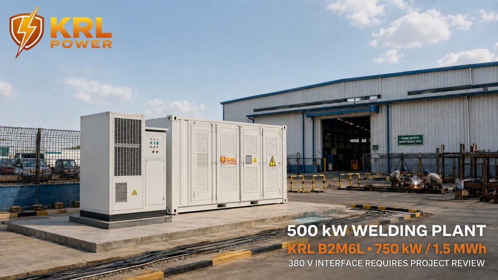
Those two ratios support preliminary selection. Purchase approval still depends on the welders’ input kVA, power factor, current waveform, duty cycle, simultaneous-operation pattern and the proposed 380 V connection. The public B2M6L table lists 400/230 V CA, de sorte que la conception électrique définitive doit tenir compte de l'interface 380 V/400 V avant que la commande ne soit validée.
Six contrôles de projet présentent les risques les plus élevés en matière d'interruption d'activité et de rupture de contrat :
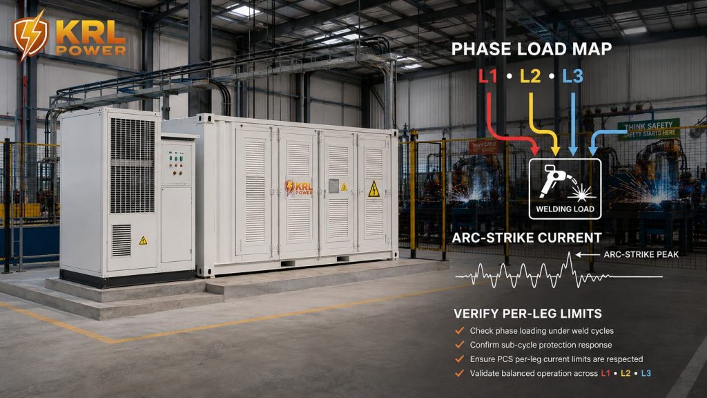
- la charge phase par phase et l'enveloppe de charge déséquilibrée du PCS ;
- courant de coup de foudre par arc de sous-cycle par rapport à la limite de courant instantanée du PCS ;
- le courant d'appel à la magnétisation du transformateur et l'impédance de la source sur le bus de 380 V ;
- réaction du groupe électrogène diesel et du système de stockage d'énergie par batterie (BESS) en cas d'arcs électriques et de coupure soudaine de la charge ;
- la limitation de la production photovoltaïque lorsque la batterie est pleine et que la charge de production diminue en mode îlot ; et
- cellule, circuit intermédiaire et acceptation en garantie du cycle de soudage pulsé mesuré.
| Point à trancher | Exigences du client | Référence KRL publiée | Conclusion relative à la passation de marché |
|---|---|---|---|
| Charge de production globale | 500 kW | Puissance nominale de 750 kW en réseau et hors réseau | Une marge de puissance nominale de 250 kW est disponible à la puissance nominale indiquée |
| Groupes de production | Three groups at 150–200 kW | 1 130 A : courant alternatif maximal pour la configuration de 1,5 MWh | Vérifier le chevauchement des groupes, le kVA et le courant transitoire |
| Bus obligatoire | 380 V triphasé | 400/230 V CA, L1/L2/L3/N/PE | Définir le transformateur, le réglage des prises ou la plage de tension de fonctionnement homologuée |
| Cible de stockage | 1 500 kWh | 1,5 MWh d'énergie nominale | Trois heures : c'est le calcul arithmétique de la puissance nominale à 500 kW |
| Installation | Site industriel en plein air | Batterie IP65 ; refroidissement par liquide ; système de protection contre les incendies homologué | Vérifier la protection à l'échelle de l'enceinte et la conception anti-incendie du site |
| Demande de garantie | Garantie de cinq ans sur la batterie | Les conditions de garantie spécifiques à chaque modèle ne sont pas rendues publiques. | Joindre au contrat l'annexe de garantie signée |
Buyers can compare the public product range on KRL Power’s Page consacrée aux systèmes de stockage d'énergie à usage commercial et industriel et passer en revue les éléments sélectionnés Configurations B2M6L de 1,5 MWh et 2 MWh.
Convertir la valeur de 500 kW en un programme d'exploitation
La puissance totale de 500 kW correspond à une limite du système. Elle ne précise pas comment l'usine atteint cette valeur. Trois groupes de production d'une puissance comprise entre 150 kW et 200 kW peuvent donner lieu à plusieurs états de fonctionnement :
| Groupes de production actifs | Charge connectée possible | Ce que les contrôles doivent permettre de déterminer |
|---|---|---|
| Un | 150–200 kW | Mode de fonctionnement stable minimal et charge auxiliaire |
| Deux | 300–400 kW | Chevauchement normal de la production et puissance de charge disponible |
| Trois | 450–600 kW | Chevauchement maximal autorisé, pics de courte durée et priorité en matière de délestage |
Le service de gestion des urgences (EMS) devrait disposer d’un tableau simple des priorités d’intervention. Un planning concret précise :
- les équipements qui doivent rester sous tension en permanence ;
- des soudeurs qui pourraient commencer ensemble ;
- compresseurs, ventilateurs d'extraction, pompes et équipements de refroidissement associés à chaque groupe ;
- la durée maximale du chevauchement entre trois groupes ;
- les charges pouvant être mises en veille en cas de coupure de courant ;
- la séquence de redémarrage après une coupure du réseau ;
- le niveau de charge minimal de la batterie requis pour un arrêt en toute sécurité.
Ce barème permet d'éviter qu'une moyenne de 500 kW ne soit confondue avec une puissance maximale de 500 kW. Il fournit également à l'usine une règle claire pour fonctionner dans les limites de puissance du BESS.
Sur le schéma unifilaire, séparez le bus d’alimentation de soudage des charges de commande sensibles. Les automates programmables, les relais de sécurité, les commutateurs réseau, les bobines de contacteurs et les contrôleurs de soudeuses doivent disposer d’une capacité de maintien de tension documentée. KRL indique un temps de commutation inférieur à 10 ms pour le modèle B2M6L ; le plan de mise en service doit vérifier que chaque commande critique reste stable pendant toute la durée de la transition effective. Une alimentation de secours (UPS) dédiée ou une alimentation de commande en courant continu peut être nécessaire pour les appareils dont la tolérance de maintien en fonctionnement est plus courte.
Enregistrer les charges de soudage en kVA, kW et en intensité
Welding equipment is frequently specified in input kVA, output current and duty cycle. A BESS proposal based only on the welders’ output rating can miss the electrical input demand. The load register should record the following fields for every major machine:
- marque et modèle ;
- tension d'entrée et configuration de phase ;
- puissance nominale d'entrée en kVA et en kW ;
- facteur de puissance aux paramètres de soudage prévus ;
- courant d'entrée maximal ;
- rapport cyclique ;
- le courant de démarrage ou de magnétisation, le cas échéant ;
- données relatives aux courants harmoniques pour les postes à souder à onduleur ;
- disjoncteur en amont et section du câble ;
- groupe opérationnel et durée prévue du chevauchement.
À 380 V triphasé, 500 kW correspondent à environ 760 A avec un facteur de puissance de 1,0. À un facteur de puissance de 0,85, le courant atteint environ 894 A. Voici des exemples de calcul basés sur la relation triphasée standard :
Current = Active power ÷ (√3 × line voltage × power factor)
KRL publie 1 130 A de courant alternatif maximal pour la configuration B2M6L de 1,5 MWh. La comparaison des courants reste préliminaire, car la tension du réseau publiée est de 400/230 Vca et les posteuses utilisées peuvent produire un courant déformé. La conception validée devra s’appuyer sur les données mesurées de courant efficace, de facteur de puissance et d’harmoniques issues de cycles de production représentatifs.
Associer chaque poste de soudage aux phases auxquelles il est raccordé
The load register must identify how each welder is connected. A factory described as “three-phase” can still contain large single-phase or line-to-line welders connected to L1–N, L2–N, L3–N, L1–L2, L2–L3 or L3–L1. Total kW can remain below the PCS rating while one inverter leg reaches its current limit.
Notez ces valeurs pour chaque soudeur principal et chaque état de production :
- connexion d'entrée et paire de phases ;
- courant efficace par phase ;
- crête de courant d'arc et durée d'impulsion sur chaque phase ;
- courant de neutre lorsqu'un neutre est utilisé ;
- les courants de séquence positive, négative et zéro, le cas échéant ;
- nombre maximal de soudeurs pouvant travailler simultanément par phase ; et
- déséquilibre de tension mesuré au niveau du bus de l'usine.
Le dossier de demande d'agrément PCS doit indiquer :
- limite de courant en service continu et en service de courte durée pour chaque branche de phase ;
- intensité et durée admissibles du courant de séquence négative ;
- capacité de traitement des séquences zéro et limite de courant neutre pour la topologie proposée ;
- objectif de régulation du déséquilibre de tension en mode îlot ;
- réduction de la puissance nominale dans les conditions de charge déséquilibrée requises ; et
- réponse de protection lorsqu'une phase atteint sa limite avant que la puissance totale n'atteigne 750 kW.
A requirement such as “100% unbalanced load” is usable only when the contract defines the phase currents, duration, neutral arrangement and acceptance limits. If the offered PCS cannot support the measured phase concentration, the design must redistribute welders among phase pairs, separate selected loads, add a manufacturer-approved balancing solution or change the PCS architecture. The FAT and SAT should reproduce the approved worst-case phase combination.
Utilisez correctement les limites B2M6L publiées
KRL’s public table supports the following 1.5 MWh configuration:
| Article publié | Configuration KRL B2M6L de 1,5 MWh |
|---|---|
| Modèle | KRL-B1M5L-750H3S-720M6-HX1 |
| Composition chimique des batteries | LiFePO4 |
| Puissance nominale | 1,5 MWh |
| Tension nominale / capacité | 832 V / 1 884 Ah |
| Puissance nominale en réseau | 750 kW |
| Puissance nominale en mode hors réseau | 750 kW |
| Tension alternative | 400/230 V CA, L1/L2/L3/N/PE |
| Fréquence nominale | 50/60 Hz |
| Courant alternatif maximal | 1 130 A |
| Temps de commutation | <10 ms |
| Puissance photovoltaïque maximale | 720 kW |
| Canaux MPPT | Six |
| Plage de tension MPPT | 250–850 Vdc |
| Tension photovoltaïque maximale | 950 Vcc |
| Courant d'entrée photovoltaïque | 200 A × 6 |
| Communication | RS485 / Wi-Fi |
| Refroidissement | Refroidissement par liquide pour la batterie ; refroidissement intelligent pour le PCS |
| Plage de conditions environnementales | −10°C to 55°C; 5–95% RH; below 2,000 m |
| Dimensions / poids approximatif | 6,058 × 2,438 × 2,896 mm / 15,000 kg |
The product-page title refers to a broader “1–2 MW / 2–6 MWh” family, while its table publishes only 1.5 MWh / 750 kW and 2 MWh / 1 MW configurations. The article and quotation should use the tabled model. Any 1.2 MW or 2.6 MWh offer requires a separate manufacturer-issued data sheet.
KRL’s Présentation de la solution C&I ESS fournit un contexte architectural plus large. L’exécution du contrat doit rester strictement conforme au modèle B2M6L et aux documents du projet.
Fermer l'interface 380 V et 400 V avant l'achat
Les spécifications d'usine indiquent une alimentation triphasée de 380 V. Le tableau public B2M6L indique 400/230 V CA. Cette différence a une incidence sur le courant, le rapport de transformation, les réglages de protection et la puissance disponible au niveau du bus client.
À 400 V et avec un facteur de puissance de 1,0, une puissance de 750 kW génère environ 1 083 A. À 380 V, cette même puissance de 750 kW génère environ 1 139 A, soit une valeur légèrement supérieure au courant alternatif maximal publié de 1 130 A. Ce calcul montre pourquoi le devis doit préciser à la fois la tension de raccordement et la limite de courant.
Le schéma unifilaire approuvé doit indiquer :
- la tension aux bornes CA du système BESS ;
- la plage de tension nominale et admissible du bus principal de l'usine ;
- si un transformateur ou un transformateur à prises est inclus ;
- courant continu à la tension du bus sélectionnée ;
- contribution au court-circuit et coordination des protections ;
- dispositif de neutre et de mise à la terre ;
- le nombre de câbles, la section des conducteurs et la longueur maximale du tracé ;
- chute de tension à charge normale et à charge maximale de production ;
- séquence de commutation entre le réseau public, le groupe électrogène et le système de stockage d'énergie par batterie (BESS), lorsque ces sources sont disponibles.
A quotation that says “380/400 V compatible” without a model-specific drawing leaves a material interface unresolved.
Démontrer la séquence de démarrage à froid du transformateur
Si un transformateur est installé entre le système de couplage au réseau (PCS) et le bus de production de 380 V, la séquence de rétablissement hors réseau doit tenir compte du courant d'appel de magnétisation du transformateur. Les sources basées sur des onduleurs sont limitées en courant, et la mise sous tension d'un transformateur hors tension peut provoquer un effondrement de la tension ou le déclenchement des protections lorsque le PCS, le transformateur et le mode de commutation sont mal coordonnés.
Le fournisseur doit définir la méthode choisie :
- Rampe de tension PCS ou mise sous tension commandée par le flux ;
- prémagnétisation du transformateur ;
- fermeture contrôlée du disjoncteur « point-sur-onde » ou par étapes ;
- impédance pré-insertion ;
- mise sous tension par le réseau électrique ou le groupe électrogène avant le transfert ; ou
- une autre séquence approuvée par le constructeur et étayée par des résultats d'essais.
Approval requires the actual transformer magnetizing curve, residual-flux assumption, PCS instantaneous current limit, protection thresholds and cable data. The FAT or SAT should energize the offered transformer from a de-energized bus under the approved worst-case sequence. KRL’s public B2M6L table does not publish a transformer black-start capability, so this function must be confirmed for the offered project configuration.
Calcul de l'impédance de la source et de la chute de tension due à un arc électrique
Le transformateur reste dans le circuit après la mise en service. Son impédance en pourcentage, la résistance de ses enroulements et sa réactance de fuite s’ajoutent à l’impédance du filtre de sortie du PCS, des câbles, de l’appareillage de commutation et des barres omnibus. Une impulsion de soudage importante entre phases peut donc provoquer une chute de tension plus importante au niveau de la barre omnibus de production de 380 V que ne le prévoit un calcul de puissance en régime permanent.
L'étude électrique doit fournir :
- puissance nominale du transformateur, groupe vectoriel, prise, perte en charge et impédance en pourcentage ;
- impédance de sortie du PCS en séquence positive et négative ou modèle dynamique validé ;
- résistance et réactance des câbles et des barres omnibus ;
- capacité de court-circuit triphasé et phase-à-phase au niveau du bus de soudage ;
- rapport de court-circuit sur la base de la puissance convenue pour le projet ;
- la chute de tension et la remontée prévues pour la forme d'onde mesurée lors de l'amorçage de l'arc ; et
- limites de tolérance de tension des postes de soudage, des automates programmables et des contacteurs.
Le rapport de court-circuit ne suffit pas à lui seul à caractériser un bus d'onduleur à courant limité. La décision finale doit s'appuyer à la fois sur le calcul de l'impédance, sur une étude des transitoires électromagnétiques ou une étude dynamique validée par le fabricant, ainsi que sur un essai de chute de tension réalisé en présence de témoins.
Une configuration PCS native de 380 V approuvée par le fabricant peut permettre de supprimer l'impédance supplémentaire du transformateur. Cette option ne peut être sélectionnée que si KRL fournit le numéro de modèle correspondant, l'intensité nominale, les paramètres de protection, les limites de certification et la garantie. La configuration B2M6L 400/230 V CA publiée ne doit pas être modifiée par le biais d'un réglage supposé du micrologiciel.
Calculer la durée d'exécution à partir de l'état réel de la production
L'arithmétique nominale fournit une référence supérieure utile :
| Charge moyenne admissible | Valeur nominale de 1,5 MWh (calcul arithmétique) |
|---|---|
| 300 kW | 5,0 heures |
| 400 kW | 3,75 heures |
| 500 kW | 3,0 heures |
| 600 kW | 2,5 heures |
These values divide nominal battery energy by average load. Available AC runtime will be lower after applying the project’s usable state-of-charge window, conversion losses, auxiliary consumption, temperature limits, reserve state of charge and capacity-aging criterion.
Le cahier des charges d'achat devrait donc définir la durée d'exécution à l'aide d'une équation transparente :
Required nominal energy = (average supported load × required hours + auxiliary energy) ÷ approved usable-energy factor
The usable-energy factor must come from the signed technical schedule. KRL’s public page does not state usable AC energy, round-trip efficiency for this model or end-of-life retained capacity. Those values belong in the quotation and acceptance test.
Vérification de la qualité de l'alimentation électrique et des performances dynamiques du soudage à l'arc
La différence de 250 kW entre la puissance nominale de 750 kW du PCS et la charge totale déclarée de 500 kW offre une marge de sécurité en régime permanent. L'acceptabilité dynamique nécessite des preuves distinctes. Le courant de soudage peut varier rapidement, et la réponse dépend de la topologie du poste de soudage, des réglages de commande, du taux de service et de la puissance du bus CA.
L'examen technique doit porter sur les éléments suivants :
- un enregistrement de la qualité de l'alimentation électrique sur sept jours au niveau de l'entrée d'alimentation de l'usine ;
- les tendances de la puissance active et de la puissance apparente sur une seconde pour la planification de la production ;
- l'acquisition à haute vitesse des formes d'onde lors d'arcs électriques représentatifs, selon une méthode d'échantillonnage convenue entre le PCS et les fournisseurs de postes de soudage ;
- enregistre les baisses de tension et les reprises de tension lors du démarrage de groupes importants ;
- déséquilibre de courant entre les trois phases ;
- la distorsion harmonique totale et les harmoniques dominantes individuelles ;
- déplacement et facteur de puissance réel ;
- demande maximale simultanée des groupes ;
- Courbe de surcharge du PCS et durée ;
- limites de régulation de la tension et de la fréquence en mode hors réseau.
Acceptance criteria should use measurable values at the point of common coupling. Marketing descriptions such as “handles industrial surge” cannot replace the overload curve, power-quality limits and witnessed test procedure.
L'essai en présence de témoins doit reproduire les conditions de production convenues : un groupe de soudure, deux groupes se chevauchant, le chevauchement maximal approuvé et la séquence de redémarrage contrôlée. Enregistrer la tension, la fréquence, le courant de phase, la puissance en kW et en kVA, le facteur de puissance et la réponse harmonique, en les comparant aux limites d'acceptation horodatées.
Courant de déclenchement de l'arc lors d'un sous-cycle d'essai
Le courant RMS et les tendances sur une seconde ne permettent pas de décrire les premières millisecondes d'un arc électrique. Un pic de courant de courte durée peut atteindre la limite de courant matérielle du PCS avant que les commandes de supervision, plus lentes, ne réagissent. Le cahier des charges d'achat doit donc prévoir :
- courant de crête et durée d'impulsion aux bornes du PCS ;
- la limite de la zone de fonctionnement sûr du semi-conducteur PCS et le seuil de surintensité matériel ;
- une fonction de protection rapide indépendante, telle que la détection de désaturation du circuit d'attaque de grille, un comparateur analogique, une limitation du courant de crête cycle par cycle ou un circuit équivalent approuvé par le fabricant ;
- temps de réponse de la protection, intervalle de suppression, comportement de coupure progressive et séquence de rétablissement ;
- la coordination entre la protection matérielle et la boucle de régulation de courant du DSP ;
- fréquence de répétition des impulsions autorisée et limite d'accumulation thermique ;
- le comportement de déclenchement lorsque plusieurs soudeurs allument simultanément l'arc ; et
- les enregistrements réalisés à l'aide d'un oscilloscope ou d'un analyseur de puissance à haute vitesse lors de l'essai auquel on a assisté.
Une protection matérielle rapide peut prévenir les dommages en coupant un dispositif de puissance. Une production continue nécessite un deuxième résultat : le PCS doit limiter le courant d’arc, maintenir le bus CA dans la plage de tension convenue et se rétablir sans déclenchement inacceptable à l’échelle de l’installation. Le fournisseur peut protéger ses circuits propriétaires tout en fournissant un schéma fonctionnel de protection signé, un tableau des seuils, des données sur les temps de réponse et des formes d’onde certifiées.
The acceptance test should use representative welders or a validated load emulator. Passing a steady-state 500 kW test does not prove arc-strike performance. KRL’s public product table does not state a sub-cycle current envelope or hardware-protection architecture, so the supplier must provide model-specific evidence before the system is released for production duty.
Sélectionnez le mode de fonctionnement en fonction des priorités de production
La séquence de contrôle doit refléter la manière dont la ligne de soudage génère des bénéfices. Voici une hiérarchie pratique :
- Maintenir les charges essentielles liées aux systèmes de commande, de sécurité, d'extraction et de refroidissement.
- Veillez à ce que les groupes de soudage prévus respectent les limites approuvées en termes de kW, de kVA et d'intensité.
- Utiliser l'énergie disponible du réseau ou l'énergie photovoltaïque pour recharger tout en protégeant le bus de production.
- Démarrer un groupe électrogène existant lorsque le seuil de charge convenu est atteint ou en cas de coupure prolongée.
- Éliminer les groupes de moindre priorité avant que le BESS n'atteigne sa limite de protection.
- Restaurer les groupes de production selon une séquence contrôlée après la restauration de la source.
Si l'usine dispose d'un groupe électrogène diesel, l'offre doit préciser sa puissance nominale en kVA, sa charge minimale stable, le fonctionnement du régulateur de tension, le contrôle de fréquence, la capacité de charge par paliers et la limite de charge. KRL mentionne un port pour groupe électrogène diesel sur le modèle B2M6L, tandis que la page publique ne précise pas la compatibilité avec tous les groupes électrogènes ni la séquence de commande finale.
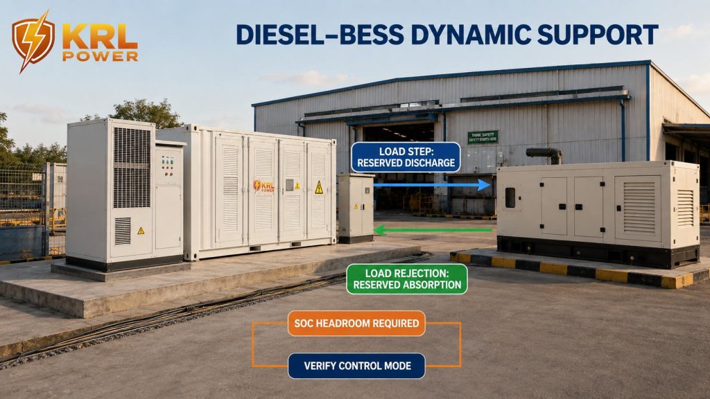
Define Diesel–BESS Dynamic Support
Le générateur et le système de stockage d'énergie par batterie (BESS) doivent disposer d'un manuel d'exploitation signé prévoyant les coupures de réseau. Le mode de commande retenu doit préciser quelle source assure la tension et la fréquence, comment la puissance active et la puissance réactive sont réparties, et comment chaque source réagit au démarrage ou à l'arrêt d'un arc de soudage.
Le programme de contrôle doit définir :
- réglages du régulateur du générateur et du régulateur automatique de tension ;
- charge minimale stable du générateur, charge par paliers autorisée et limite de rejet de charge indiquées par le fournisseur du moteur ;
- Rôle de BESS en tant que générateur de réseau ou en mode de suivi du réseau dans chaque état de fonctionnement ;
- réglages de réduction ou de répartition de la puissance active et réactive ;
- plage d'état de charge de la batterie réservée à la fois à la décharge et à l'absorption ;
- décharge rapide du BESS lors d'une augmentation autorisée de la charge de soudage ;
- Charge du BESS ou réduction de la puissance après un rejet soudain de la charge de soudage ;
- protection contre les inversions de puissance, les surfréquences, les sous-fréquences et les problèmes de synchronisation ;
- les transitoires lors du démarrage, de l'arrêt ou du déclenchement du générateur ; et
- récupération une fois que la batterie BESS a atteint sa limite de charge ou de décharge.
La plage de charge réservée est importante car une batterie pleine ne peut pas absorber un rejet de charge important et une batterie déchargée ne peut pas supporter une augmentation des arcs électriques. Le système de gestion de l'énergie (EMS) doit maintenir une marge de puissance bidirectionnelle suffisante pour l'état de production convenu.
L'essai de prise en charge du générateur doit consister à activer et désactiver le groupe de soudage le plus puissant homologué alors que le générateur est en service. Enregistrer la puissance (kW), la puissance réactive (kvar), la fréquence, la tension, la vitesse ou la réponse du régulateur du générateur, ainsi que la puissance (kW) et la puissance réactive (kvar) du BESS, son état de charge et la limitation de courant du PCS. Répéter l'essai aux points de fonctionnement convenus avec le fabricant du générateur.
Active filtering, virtual-synchronous-machine control and fast bidirectional generator support are separate capabilities. KRL’s public B2M6L table does not confirm these functions. Include them only when the offered PCS and EMS documents define the mode, limits and acceptance test.
KRL’s published Solution industrielle hors réseau et hybride diesel au Nigeria peut aider à structurer la discussion technique. La conception de l'installation de soudage nécessite toutefois ses propres données de charge et son schéma unifilaire.
Considérer l'entrée photovoltaïque de 720 kW comme une interface disponible
Le tableau B2M6L sélectionné répertorie une puissance d'entrée photovoltaïque pouvant atteindre 720 kW répartie sur six canaux MPPT. L'usine peut acquérir le système de stockage d'énergie (BESS) avant l'installation complète du parc photovoltaïque, à condition que l'architecture finale soit compatible avec le plan de mise en service prévu.
Pour une option photovoltaïque, le projet doit préciser :
- puissance installée en courant continu et production annuelle prévue ;
- tension en circuit ouvert de la chaîne à la température minimale du site ;
- operating voltage within the 250–850 Vdc MPPT range;
- courant par MPPT dans la limite d'entrée publiée de 200 A ;
- sur un toit ou au sol ;
- hypothèses relatives aux coupures et aux réductions ;
- autoconsommation pendant la production ;
- puissance de charge disponible après avoir alimenté la charge active de l'usine.
La capacité photovoltaïque ne détermine pas à elle seule l'autonomie de secours. L'état de charge de la batterie au moment d'une coupure de courant, la production solaire en temps réel et le programme de production en cours déterminent la durée disponible.
Gestion des excédents photovoltaïques en mode îloté
Lorsque le niveau de charge de la batterie est élevé, la production photovoltaïque peut dépasser la charge de soudage en cours et les charges auxiliaires. Les commandes du système de gestion de la batterie (EMS) et de l'onduleur doivent réduire la puissance photovoltaïque entrante avant que la batterie, le circuit intermédiaire CC ou le système de conversion de puissance (PCS) n'atteigne un seuil de protection.
Le programme de contrôle doit définir :
- le seuil de niveau de charge à partir duquel la réduction de la production photovoltaïque commence ;
- Commandes de réduction de puissance MPPT et de mise à zéro de la puissance en mode hors réseau ;
- réaction face à l’arrêt soudain d’un ou plusieurs groupes de soudage ;
- plage de tension admissible du circuit intermédiaire et seuils de déclenchement des dispositifs de protection ;
- capacité de charge de réserve maintenue pour permettre un rejet rapide de la charge ;
- en coordination avec un groupe électrogène diesel en service ; et
- redémarrer la logique après une limitation de la production photovoltaïque ou un déclenchement de protection.
Le SAT doit reproduire un événement caractérisé par une puissance photovoltaïque élevée et un état de charge élevé, puis supprimer le palier de charge de soudage convenu. Enregistrer la puissance photovoltaïque, la puissance de la batterie, la tension du bus CC, la tension CA et la réponse du système de contrôle. Le tableau public B2M6L répertorie la puissance d’entrée photovoltaïque nominale et les limites MPPT, mais ne publie pas cette séquence de limitation en mode îlot ; celle-ci doit figurer dans le cahier des charges du projet et la procédure de réception.
Préciser les mesures de protection extérieure et les travaux sur le chantier
La table publique B2M6L répertorie Indice de protection IP65 pour la batterie. Il n'est pas précisé que tous les compartiments PCS, connecteurs, presse-étoupes, panneaux auxiliaires et interfaces installées sur site présentent le même indice de protection. Le contrat doit préciser l'indice de protection (IP) de chaque boîtier livré.
Pour un site industriel nigérian situé à l'extérieur, le kit d'installation doit comprendre :
- niveau de la fondation achevée, capacité portante et drainage ;
- delivery route for a container measuring 6,058 × 2,438 × 2,896 mm;
- méthode de levage pour un système pesant environ 15 000 kg ;
- autorisations d'accès pour les services et accès d'urgence ;
- évaluation de l'ensoleillement et de la température ambiante ;
- poussière, pluie, corrosion et exposition aux inondations ;
- protection contre la foudre et mise à la terre ;
- interfaces de détection, d'extinction, d'isolation et d'intervention d'urgence en cas d'incendie ;
- détails relatifs aux tranchées de câbles, aux presse-étoupes et aux joints d'étanchéité ;
- sécurité, éclairage et contrôle d'accès.
KRL lists liquid cooling, a fire-protection system and operation from −10°C to 55°C. Final thermal performance requires the project derating curve, auxiliary-power schedule and approved maintenance clearances.
Le Présentation des essais et de la certification KRL peuvent étayer une demande de justificatifs. Les acheteurs doivent se procurer les certificats et les rapports d'essai qui identifient le modèle proposé, les limites du système applicables et la version du document.
Déterminer le rapport cyclique côté batterie
Les rapports puissance/énergie au niveau du système sont d'environ 0,33 °C à 500 kW et 0,5 °C à la puissance nominale publiée de 750 kW, en prenant 1,5 MWh comme référence énergétique nominale. Ces rapports décrivent le fonctionnement moyen du système. Les cellules peuvent être soumises à une forme d'onde différente, car le circuit intermédiaire en courant continu du PCS, les commandes de commutation, les filtres, les chaînes en parallèle et les équipements auxiliaires modulent le courant de la batterie.
Le dossier de qualification des batteries doit préciser :
- fabricant, modèle, type de batterie et capacité ;
- courant de charge et de décharge continu dans la plage de températures du projet ;
- courant de charge et de décharge de courte durée autorisé, avec des limites de temps ;
- courant d'ondulation RMS admissible et plage de fréquences applicable ;
- La capacité du circuit intermédiaire et l'approche de filtrage du courant de batterie ;
- limites de courant des modules, des racks, des barres omnibus et des contacteurs ;
- les températures mesurées de la cellule, des bornes et du liquide de refroidissement pendant l'essai par impulsions ; et
- Fréquence d'échantillonnage du système de gestion de bâtiment (BMS), seuils d'alarme et résolution des événements enregistrés.
Utilisez le spectre de courant mesuré côté batterie pour choisir la solution. Les mesures possibles peuvent inclure l’ajout d’une capacité en parallèle, l’utilisation d’une cellule dont l’enveloppe de puissance supérieure a été vérifiée, l’augmentation de la capacité du bus CC ou du tampon d’impulsions, la révision des commandes du PCS ou la modification de l’ordre de mise en charge en production. Chaque option nécessite des données thermiques et de durée de vie spécifiques au modèle.
KRL’s public B2M6L table identifies LiFePO4 chemistry, 832 V and 1,884 Ah. It does not publish the cell model, continuous cell Taux C, pulse Taux C or ripple-current envelope. The proposed system should therefore remain described as an LFP configuration until KRL supplies the exact cell and verified pulse-duty data. A solid-state or semi-solid-state alternative should enter the proposal only with a container-scale model number, electrical ratings, safety evidence, warranty and delivery scope for this application.
Définir la garantie de cinq ans en termes quantifiables
Une demande de garantie de cinq ans sur la batterie doit prendre la forme d'une annexe signée comprenant :
- modèle du produit couvert par la garantie et plage de numéros de série ;
- date de début de la garantie ;
- niveau minimal d'énergie utilisable ou d'état de santé ;
- cycles annuels autorisés ou débit énergétique cumulé ;
- profondeur de déversement autorisée ;
- limites de température de fonctionnement et d'état de charge ;
- obligations en matière de surveillance et de maintenance à distance ;
- exclusions liées aux incidents sur le réseau, aux conditions du site et aux réglages non autorisés ;
- délai d'intervention, responsabilité en matière de pièces de rechange et étendue des prestations de main-d'œuvre ;
- méthode d'essai permettant de vérifier une allégation relative à la capacité ;
- profil de charge admissible pour le soudage par impulsions, courant de crête de la batterie et ondulation du courant ;
- traitement des variations de charge fréquentes dans la comptabilité des cycles et des débits ;
- mesures correctives, procédures d'escalade et documents contractuels applicables.
Les variations rapides de la puissance de soudage ne prouvent pas automatiquement que les cellules subissent des microcycles de charge-décharge identiques. Le circuit intermédiaire CC du PCS, la bande passante de commande et le filtrage peuvent modifier la forme d'onde côté batterie. Avant l'attribution du marché, enregistrez les impulsions de soudage côté CA et obtenez la réponse correspondante en termes de courant de batterie et de réponse thermique à partir d'une simulation ou d'un essai réalisé en présence de témoins.
The warranty should explicitly accept the approved welding duty and identify the limits that will be checked in BMS and EMS records. This prevents a later dispute over pulse rate, current ripple, temperature, state of charge or event logging. The public B2M6L page does not publish a five-year model-specific warranty or a welding-duty warranty envelope. The final contract should carry the requested term and the corresponding performance conditions. KRL’s Présentation de l'entreprise et de ses activités de fabrication fournit des informations générales sur le fournisseur ; la garantie signée reste le document faisant autorité.
Comparer les limites du devis complet
Un numéro d'équipement EXW ne peut être comparé qu'une fois que tous les fournisseurs ont répondu au même tableau de périmètre.
| Devis | Champ obligatoire |
|---|---|
| Système de batterie | Modèle exact, puissance nominale et puissance utile, système de gestion de la batterie (BMS), équipements de refroidissement et de lutte contre l'incendie |
| Conversion d'énergie | Modèle PCS, puissance continue en kW/kVA, courbe de surcharge et capacité de fonctionnement hors réseau |
| Interface CA | Transformateurs, appareillages de commutation, ATS/STS, disjoncteurs, relais de mesure et de protection |
| Commandes | Services médicaux d'urgence (EMS), communications, télésurveillance, autorisations et périmètre de cybersécurité |
| Connexion au site | Câbles, presse-étoupes, chemins de câbles, raccordements, mise à la terre et protection contre la foudre |
| Documentation | Fiches techniques, SLD, plans, certificats, manuels et fichiers de paramètres |
| Tests | Essais de réception en usine, essais de réception sur site, essais de capacité et essais de qualité de l'énergie |
| Logistique | Lieu de livraison EXW, emballage, transport terrestre, fret maritime, assurance et formalités d'importation |
| Services du site | Fondations, grue, installation, mise en service et formation des opérateurs |
| Cycle de vie | Garantie, pièces de rechange, maintenance préventive et délais d'intervention |
KRL’s Page consacrée à l'emballage des batteries et à leur expédition à l'international is relevant to the logistics workstream. The commercial comparison should also use a common landed-cost boundary. For cost-model structure, buyers can reference KRL’s Aperçu des coûts du stockage d'énergie à usage commercial tout en remplaçant les hypothèses générales par des devis de projet.
Recommandation d'achat pour l'installation de soudage de 500 kW
Le KRL B2M6L 1,5 MWh / 750 kW la configuration répond aux exigences énoncées au stade de la présélection :
- la puissance nominale dépasse de 250 kW la charge totale indiquée de 500 kW ;
- la puissance nominale correspond à trois heures à une puissance constante de 500 kW ;
- Une puissance de 750 kW est indiquée tant pour le fonctionnement raccordé au réseau que pour le fonctionnement hors réseau ;
- le courant maximal publié de 1 130 A corrobore le calcul préliminaire en régime permanent à 500 kW ; la capacité de résistance aux arcs électriques sous-cycliques doit être justifiée par des preuves distinctes ;
- le refroidissement par liquide, une batterie conforme à la norme IP65 et un système de protection contre les incendies sont mentionnés ;
- Un port pour générateur et une interface photovoltaïque en option sont disponibles.
Validez le bon de commande une fois que le fournisseur aura franchi les étapes de validation suivantes :
- Carte de soudage phase par phase représentant les conditions de courant maximal de séquence négative et de séquence zéro.
- Vérification de la puissance en kVA, du facteur de puissance, des harmoniques, du taux de service et de la demande simultanée du poste de soudage.
- Forme d'onde de déclenchement d'arc en sous-cycle, protection matérielle indépendante et données spécifiques au modèle concernant la limitation de courant du PCS.
- Conception homologuée pour 380 V/400 V, avec résultats concernant le démarrage à froid du transformateur, l'impédance de source, la résistance des barres et les chutes de tension.
- Calcul de l'énergie utile contractuelle et de la durée de fonctionnement.
- Diesel–BESS dynamic-support sequence and load-step test, when a generator is included.
- Test de limitation de la production photovoltaïque en mode îlot et de rejet soudain de charge, lorsque le photovoltaïque est pris en compte.
- Modèle de cellule exact, enveloppe d'impulsion côté batterie et garantie de cinq ans sous réserve du respect des conditions d'utilisation approuvées.
- Tableau des indices de protection des boîtiers pour la batterie, le système de contrôle de puissance (PCS) et les interfaces de terrain.
- Matrice complète des conditions EXW et « landed-scope », avec les critères d'acceptation FAT et SAT.
For an engineered proposal, use KRL Power’s canal dédié aux solutions énergétiques sur mesure et de joindre à la demande le registre de charge, le planning de production, le schéma unifilaire et la durée d'exécution requise.
Décision commerciale
The 1.5 MWh / 750 kW B2M6L configuration deserves detailed quotation for this 500 kW Nigerian welding plant. Its public ratings create a workable preliminary power and energy envelope. Purchase approval still requires per-phase load limits, independent fast protection, the 380 V bus-strength study, diesel–BESS dynamic controls, battery-side pulse qualification, usable-energy definition, IP scope, warranty conditions and a complete balance-of-system boundary.
La finalisation de ces points permet à l'acheteur d'obtenir un devis comparatif et offre à KRL une base solide pour la réalisation du projet. La proposition qui en résulte permet de garantir la continuité de la production, de maîtriser l'intégration future de systèmes photovoltaïques ou de groupes électrogènes et d'éviter tout litige concernant le périmètre des travaux lors de l'installation.
FAQ
Une puissance de 750 kW est-elle suffisante pour une usine de soudage dont la charge totale est de 500 kW ?
Il offre une marge nominale triphasée de 250 kW par rapport à la charge totale indiquée. L'homologation exige également la prise en compte du courant par phase, de la concentration par paire de phases, de la capacité en séquence négative, de la demande simultanée et de la courbe de surcharge du PCS.
Combien de temps un système de stockage d'énergie par batterie (BESS) d'une capacité de 1,5 MWh peut-il alimenter une charge de soudage de 500 kW ?
Le calcul de l'énergie nominale donne trois heures. L'autonomie contractuelle doit tenir compte de l'énergie CA utilisable après prise en compte de la réserve, des pertes de conversion, des équipements auxiliaires, de la température et du vieillissement.
Le B2M6L peut-il être raccordé directement à un bus d'usine de 380 V ?
Le tableau public indique 400/230 V CA. La conception finale doit définir une configuration à 380 V approuvée par le fabricant ou un montage de transformateur avec des résultats concernant la limitation de courant, l'impédance en pourcentage, la résistance du bus, les chutes de tension et les protections.
Pourquoi faut-il indiquer la puissance en kVA du poste à souder alors que l'usine connaît déjà la puissance en kW ?
Le kVA reflète le courant associé au facteur de puissance. Le PCS, le transformateur, les câbles et les disjoncteurs doivent supporter le courant qui en résulte, et l'étude technique doit également prendre en compte la forme d'onde de soudage.
Comment vérifier le déséquilibre de phase sur les postes à souder de grande puissance ?
Associer chaque poste de soudage à sa phase ou à sa paire de phases, mesurer la valeur efficace par phase et le courant d'amorçage d'arc, calculer la pire combinaison simultanée et vérifier les limites PCS par branche, de séquence négative, de séquence zéro et de neutre qui s'appliquent à la topologie proposée.
La spécification de 1 130 A prouve-t-elle que le système est capable de supporter les pics de courant liés au soudage ?
Il fournit une référence de courant alternatif maximal publiée. L'homologation nécessite toutefois encore la vérification de la crête d'arc, de la durée d'impulsion par phase, de la fonction de protection matérielle indépendante, de la réponse du limiteur de courant et d'un test de soudage simultané.
L'ensemble du système B2M6L est-il conforme à la norme IP65 ?
Le tableau public indique un indice de protection IP65 pour la batterie. Obtenez les indices de protection au niveau des composants pour le PCS, les connecteurs, les panneaux auxiliaires et les interfaces de terrain assemblées.
Does KRL publicly guarantee a five-year B2M6L battery warranty?
The public product page does not state a model-specific five-year warranty. Put the requested term, capacity obligation, accepted welding-duty profile, current-ripple limits, conditions and remedy into the signed warranty schedule.
Can the system support solar PV later?
The 1.5 MWh configuration lists 720 kW maximum PV power, six MPPT channels, a 250–850 Vdc MPPT range and 200 A per channel. The final design must also define island-mode curtailment when the battery is full and PV exceeds the live load.
Can the BESS work with an existing diesel generator?
The public table lists a diesel-generator port. The project must approve generator kVA, governor and AVR settings, BESS operating mode, two-direction power reserve, load-step response, charging limit, synchronization and transition logic.
What should the factory acceptance test cover?
Verify model identity, per-phase unbalanced loading, fast hardware protection, communications, thermal controls, alarms, switching logic, arc-strike current limiting, battery-side pulse response and the approved transformer-energization sequence before shipment.
What should the site acceptance test cover?
Test the installed sources, phase imbalance, bus voltage dip, transformer black start, representative welding arcs, diesel–BESS load support, maximum group overlap, emergency isolation, runtime method and PV load rejection where those sources are installed.
Does the welding plant automatically require 1C or solid-state cells?
Select the cell and pulse-buffer solution from the measured battery-side current spectrum, RMS ripple, peak duration, temperature rise and lifetime target. KRL must provide the exact cell model and verified operating envelope for the offered container.
What BESS configuration is being evaluated for the Nigerian welding plant?
The preliminary option is the published KRL B2M6L 1.5 MWh and 750 kW configuration for a stated 500 kW aggregate load. Final selection depends on phase loading, welding transients, the 380 V interface and project acceptance evidence.
When should diesel–BESS coordination be included for a Nigerian welding factory?
Include it whenever a diesel generator will operate with the BESS during grid outages. The design must define voltage and frequency control, power sharing, charging and discharging reserve, load-step response and source transitions.
Which KRL source supports the Nigeria welding-factory product review?
The KRL B2M6L product page publishes the 1.5 MWh and 750 kW table values used for preliminary review. Project-specific functions, cell pulse limits, warranty and the 380 V connection require signed technical documents.