
A Bangladesh factory with a maximum demand of 2.7 MW needs more than a battery sized against its electricity bill. Its operating priority is to keep essential equipment running when the utility fails, start backup generation, and restore production without overloading the islanded system.
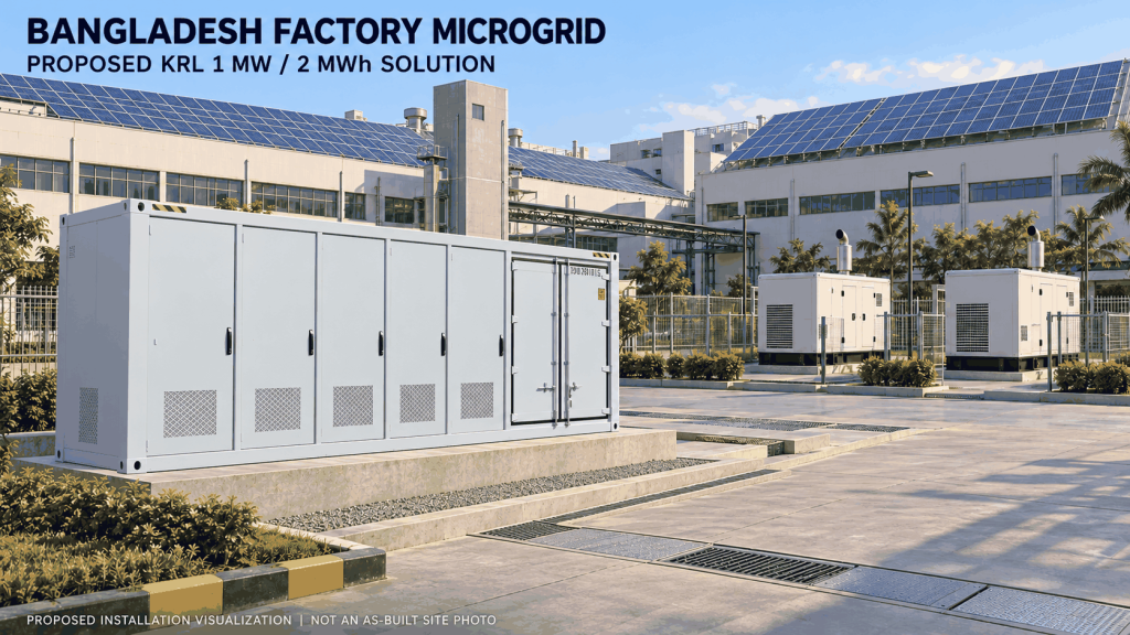
The customer brief proposes 4 MW of solar, a 1 MW / 1 MWh battery energy storage system, and two 1 MW diesel generators. For a configuration listed in KRL Power's public specification table, this proposal recommends a 1 MW / 2 MWh KRL containerized BESS, retaining the brief's load priorities and generator strategy.
This is a proposed engineering solution based on the supplied October 2026 requirements, not a completed installation or a promise of uninterrupted power to the whole factory. The larger battery is a disclosed alternative requiring customer approval.
Translate the Request into a Practical Design
| Design item | Kliëntvereiste | Proposed approach |
|---|---|---|
| Maximum factory demand | 2.7 MW | Divide feeders into three controlled priority groups |
| Solar project | 4 MW | Retain AC coupling; verify DC and AC nameplate capacities |
| BESS | 1 MW / 1 MWh | Recommend 1 MW / 2 MWh; approve the energy increase |
| Diesel generation | Two 1 MW units | Automatic start, synchronization and load sharing |
| Immediate protected demand | Up to 1 MW | Validate steady load, motor starts and reactive demand |
| Future expansion | Third generator provision | Reserve space, switchgear way and control capacity |
| Delivery objective | December, as indicated by the enquiry filename | Confirm arrival versus commissioning milestone |
Validate Tier 1 against measured startup peaks, auxiliaries, power factor and temperature derating, not just the PCS nameplate.
Recommended KRL Product and the Capacity Change
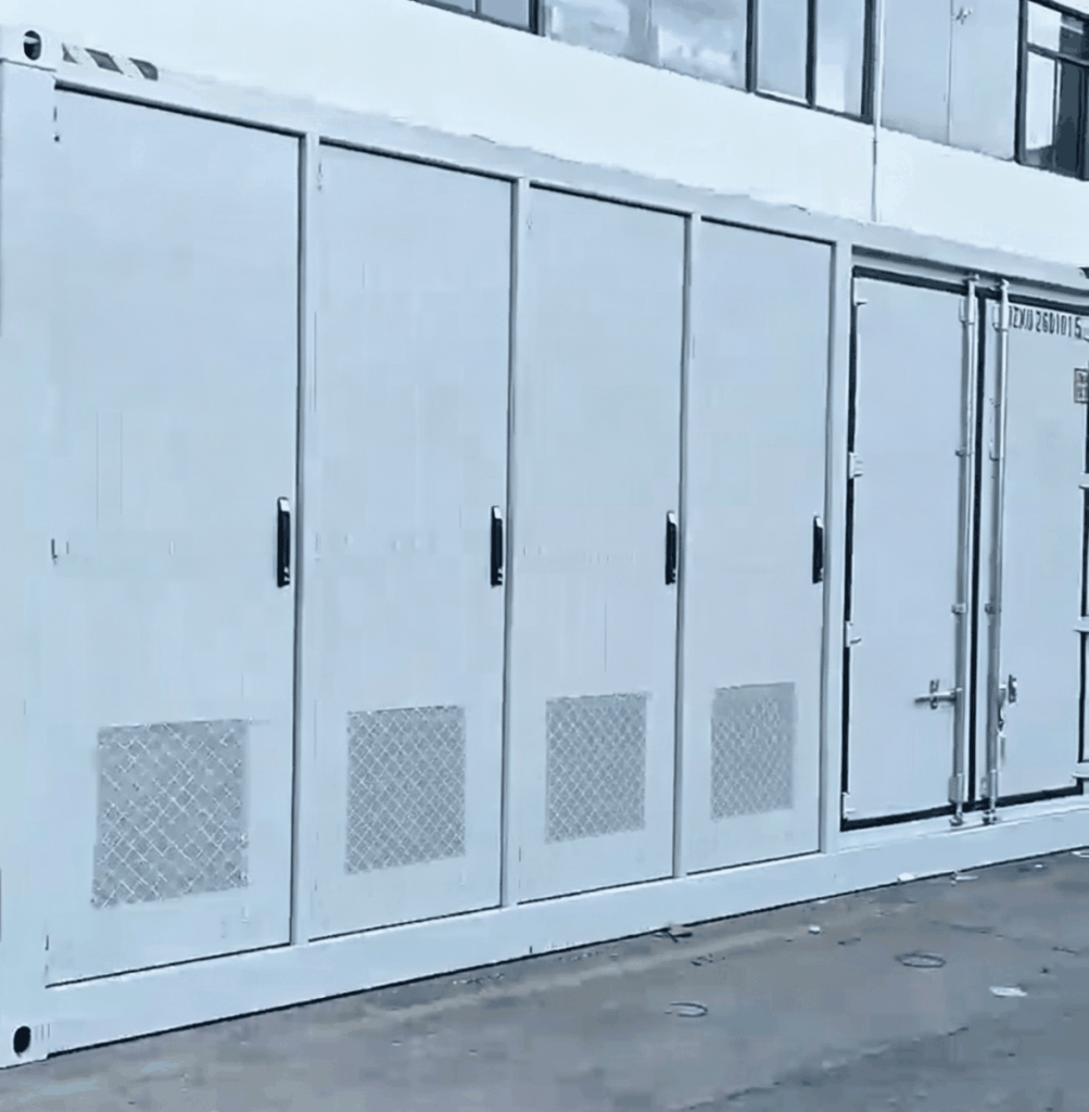
The proposed model is KRL-B2ML-1MH3S-960M8-HX1, listed in the specification table on KRL's container BESS product page. The table gives 1,000 kW AC power, 2 MWh battery energy, liquid cooling and a 960 kW integrated PV interface with eight MPPT channels. It lists a 400/230 V AC interface and switching time below 10 ms.
The page heading uses a different family capacity designation. Procurement must therefore reference the exact model and an approved datasheet, not the heading alone. The product photograph supplied by KRL identifies its 2 MWh container. Final PCS rating and interfaces remain subject to the approved model datasheet. [1]
Doubling nominal energy provides more operating reserve; it does not increase the proposed 1 MW power ceiling. If 1 MWh is a strict tender limit, request a separately engineered quotation rather than describing the recommended 2 MWh system as an exact match.
Topology: Keep the 4 MW Solar Plant on the AC Side
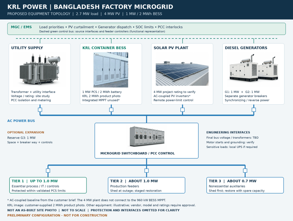
The customer's diagram uses a common AC bus. This proposal follows that architecture: the utility interface, BESS PCS, controlled PV inverters and two generator feeders each connect through appropriate protection. The MGC coordinates these sources and the priority load feeders.
The integrated MPPT remains unused in this baseline. The external PV inverters serve the separate 4 MW solar plant; they are not an extra conversion stage inserted into the BESS's integrated solar input. Connecting the entire array to that input would exceed its published limit.
Confirm whether “4 MW” describes module DC capacity or inverter AC capacity. Also confirm the factory distribution voltage. The functional diagram does not imply that the entire plant should be concentrated on one 400 V switchboard: transformer interfaces, bus sections and medium-voltage distribution may be necessary after the site study.
The EPC design must resolve neutral and earthing arrangements in both operating modes, utility isolation, synchronization checks, metering, cable routes and fault protection before equipment is ordered.
Define What Stays On During an Outage
| Priority | Planning demand | Outage response |
|---|---|---|
| Tier 1 | Up to 1.0 MW | BESS supports the validated essential-load group |
| Tier 2 | About 1.0 MW | Shed during transition; restore in controlled steps |
| Tier 3 | About 0.7 MW | Shed first and restore only with spare capacity |
Tier 1 may include IT, essential controls, lighting and selected production equipment. Each feeder needs a measured demand and an acceptable interruption time. Sensitive controls may still need a local UPS; life-safety circuits require their own applicable design review.
The transition sequence must prevent the BESS from briefly inheriting the full 2.7 MW load. PCC isolation, load shedding and grid-forming operation must be coordinated through validated protection logic, not only ordinary supervisory communications. If that coordination cannot meet the process requirement, segregate the essential bus or revise the transfer architecture.
Battery Energy: Bridge Time Is Different from Autonomy
At a constant 1 MW load, a 30-second bridge requires:
1,000 kW × 30 / 3,600 = 8.33 kWh of AC energy.
This small energy quantity does not prove that a transfer will succeed. PCS overload capability, motor behavior, breaker timing and starting SOC are equally important.
For an illustrative runtime calculation, assume a 90% usable energy window and 95% conversion efficiency. These are calculation assumptions, not verified project guarantees:
2,000 kWh × 0.90 × 0.95 = 1,710 kWh.
That corresponds to about 1.71 hours at a steady 1 MW before auxiliary consumption, aging, temperature effects and reserve restrictions. It assumes the full stated energy window is available at the start of the outage.
A reserve policy changes the result. Starting at 40% SOC and stopping at 10% leaves a 30-percentage-point window: approximately 570 kWh after the same assumed efficiency, or 34 minutes at 1 MW before other deductions. Reserve SOC must therefore follow the required failed-start and extended-outage scenario.
Two Generators Support Staged Recovery
Two 1 MW generators provide 2 MW of nominal generation. With no solar, the difference against 2.7 MW factory demand is 0.7 MW. Storage can temporarily cover a permitted shortfall, but cannot sustain it indefinitely.
The base strategy suits a factory that can reduce demand during prolonged outages. For sustained full-load night production, review a third generator or another firm-generation arrangement. Three nominal 1 MW machines still need checks for duty rating, site derating, auxiliaries and reserve; losing one leaves only 2 MW.
The brief assumes approximately 0.3 MW minimum loading for one running generator. Treat that as a provisional dispatch input. Obtain the actual engine manufacturer's permissible loading envelope and operating limits. Reverse-power protection, automatic synchronization and load sharing belong in the generator integration scope.
Control Solar Surplus and Sudden Cloud Cover
In an island, PV output must follow the system's ability to consume or absorb energy. A useful steady-state control boundary is:
PV output ≤ load − minimum running-generator output + available battery charging power.
For example, with 1.0 MW of load, a provisional 0.3 MW generator minimum and 0.5 MW of available charging power, the ceiling is 1.2 MW before additional dynamic margin. Available charging power must come from live BMS and PCS limits; it is not automatically equal to rated discharge power.
Near the upper SOC limit, absorption capability may disappear. The controller must reduce PV in advance and respond to large load rejection. Following a sudden PV loss, discharge headroom and spinning reserve must cover the gap while additional generation starts or lower-priority feeders shed.
PV should reconnect only after a stable island exists and the agreed controls permit it. Reconnection delay, ramp rate, curtailment response and communication-failure behavior must be tested with the actual inverter models.
Outage Sequence and Acceptance Testing
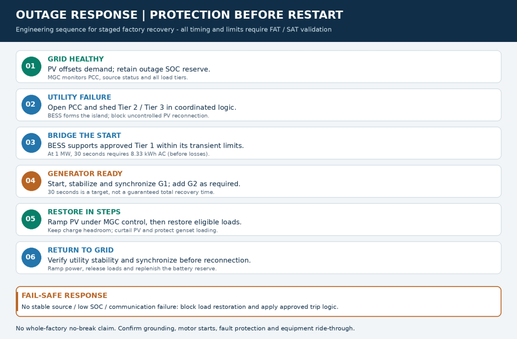
The intended sequence is utility-loss detection, isolation and load shedding; BESS support of Tier 1; generator start and synchronization; controlled solar recovery; staged load restoration; and supervised reconnection to the utility.
The brief's 30-second generator start is a target to validate, not a guaranteed time for complete factory recovery. Similarly, a product switching specification does not establish end-to-end continuity through external breakers and plant equipment.
Factory acceptance testing and site acceptance testing should cover utility loss at high demand, generator failure to start, loss of one running generator, rapid PV reduction, load rejection near maximum SOC, communication loss and grid restoration. Record voltage, frequency, feeder states, SOC and recovery time. Agree the pass criteria before testing.
Engineering and Procurement Before December Delivery
For the December objective, clarify whether the commitment means factory readiness, shipment, arrival in Bangladesh or commissioned operation. These are separate milestones, and no lead time has been verified for this proposal.
Before release, obtain the existing single-line diagram, interval load data, motor list, PV inverter details, transformer ratings, generator duty information and utility export conditions. Freeze the interface responsibilities between KRL, the PV supplier, generator supplier and EPC contractor.
Civil design must address flooding, foundations, access, fire separation, exhaust and cable entry. The illustrations do not establish surveyed installation clearances.
Request a priced bill of materials identifying the BESS, MGC, switchgear, transformer interfaces, protection, communications, commissioning, spare parts and warranty scope. Compare lifecycle economics using actual diesel consumption, tariffs, outage history and production losses rather than an unsupported payback promise.
Frequently Asked Questions
V&A
Can the proposed battery run the entire 2.7 MW factory?
Why recommend 2 MWh when the customer requested 1 MWh?
Does the 4 MW PV array connect directly to the KRL MPPT?
Will the factory have uninterrupted power during every outage?
Are two 1 MW generators enough at night?
Can the battery always charge at 1 MW?
How long can the battery supply 1 MW?
What should the customer send for a final proposal?
Why KRL for This Factory
The proposed KRL platform matches the essential-load power class while providing additional energy reserve. Procurement should pair that equipment with a defined MGC integration scope and local EPC commissioning. Require model-specific safety certificates, battery transport documentation, warranty terms and test reports; a company credential alone does not certify this installation.
Request a Site-Specific KRL Microgrid Proposal
Share the factory's electrical drawings and operating profile with KRL Power to review the 1 MW / 2 MWh option, solar interface and staged diesel strategy. The next deliverable should be an approved equipment schedule, control philosophy and test plan tied to the customer's essential-load requirement.
Source basis: customer-supplied Bangladesh microgrid requirements dated October 8, 2026; KRL public product specifications reviewed October 10, 2026. Calculations are preliminary engineering illustrations, not measured site performance.
[1] KRL container BESS product specification table: https://www.krlpower.com/battery/krl-b2m6l-1-2mw-2-6mwh/