
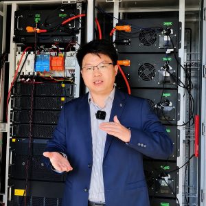
A baggage tractor clears one stand and receives its next assignment before the driver reaches the service road. On a wet ramp, the next departure still needs full pulling power, a trustworthy state-of-charge reading and a fault code the maintenance team can act on.
A custom KRL airport GSE lithium power system puts the battery pack, enclosure, BMS, thermal design and communication interface under one engineering scope. Fleet managers can plan vehicle availability with better data, and retrofit teams get a defined path from the vehicle survey to a commissioned pack.
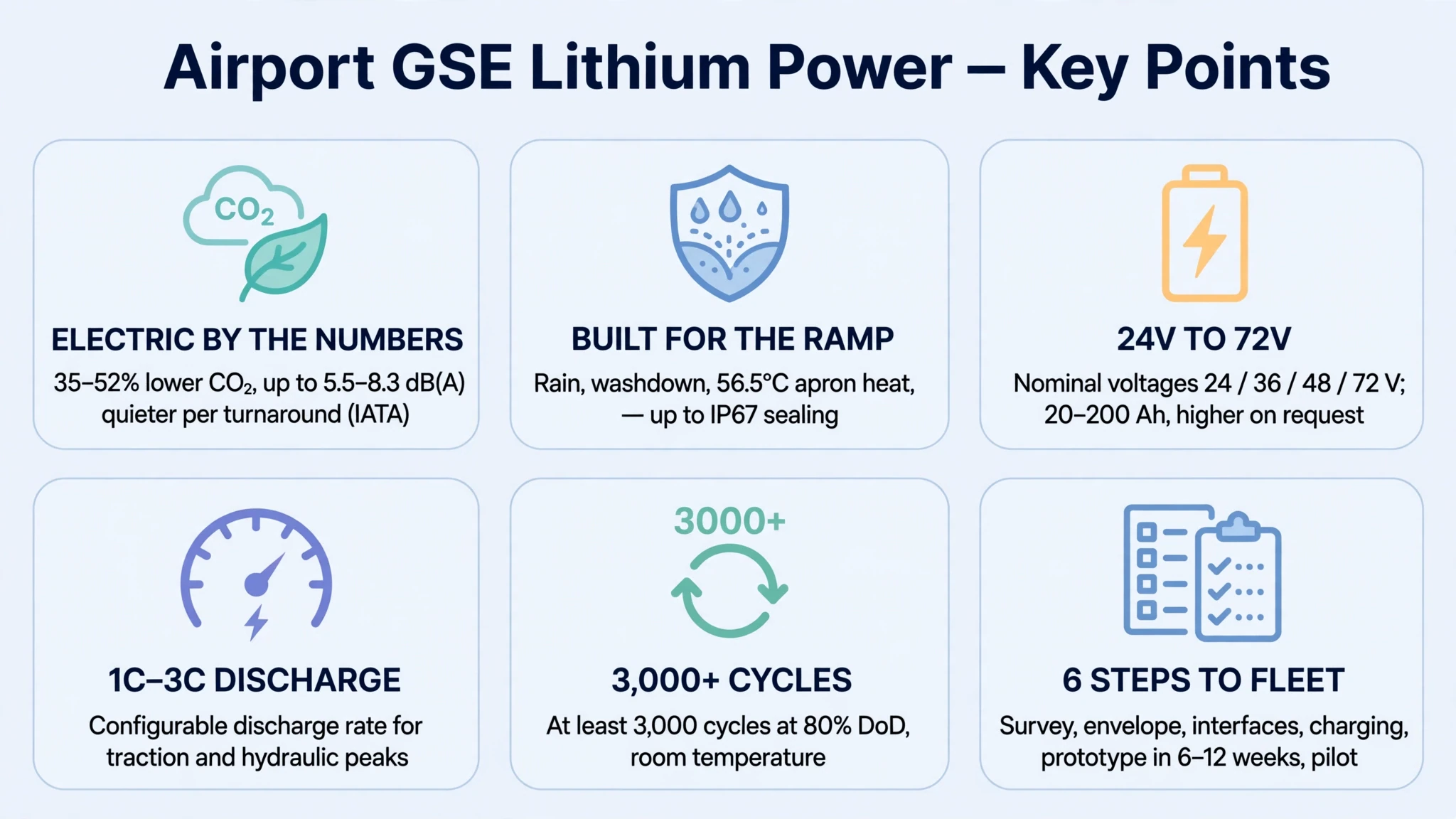
IATA reports that, in its average-EU-country scenario, electric GSE produce 35% to 52% lower CO2 emissions and up to 5.5 to 8.3 dB(A) lower noise emissions per turnaround than traditional GSE. Its transition guidance covers ramp operations, infrastructure, safety and economics because each one affects fleet deployment.
What airport GSE demands from a lithium power system
Airport GSE combines repeated acceleration, short travel cycles, towing loads, outdoor exposure and narrow charging windows. Engineers must size the system from measured duty-cycle data and then match the enclosure, thermal controls, communication interface and charger to the vehicle.
The load changes every few minutes
A baggage tractor may travel light to a stand, pull several loaded carts, stop at multiple transfer points and return for another assignment. A belt loader adds motor starts and conveyor loads. A cargo loader combines traction with repeated hydraulic lift cycles. Each task creates a different current profile.
Capacity determines how much energy the vehicle carries. Continuous current, peak current and voltage stability determine whether the pack can supply the required torque without tripping protection or starving the controller. A retrofit team needs both sets of data.
Heat, water and vibration reach the pack
A GSE pack faces rain, washdown, pavement heat and repeated shock from joints and ramps. A field study at Adelaide Airport recorded a peak apron surface temperature of 56.5°C. Cold-weather fleets may need insulation, self-heating and BMS-controlled charging.
Shift planning leaves little room for a long recovery cycle
Traditional flooded lead-acid fleets build their schedules around charging, cooling, battery changes and maintenance. For powered industrial trucks in the United States, OSHA's battery-charging guidance calls for a designated area, hydrogen ventilation, spill-response provisions and worker protection.
Lithium supports shorter planned charging windows when the selected cells, BMS and charger share an approved charge profile. KRL publishes a 1 to 2 hour charging range for its AGV battery platform, tied to capacity and charge rate.
Weight remains part of the traction system
Many traction vehicles use battery mass as part of their weight distribution. A lighter lithium pack can free space and reduce vehicle mass, yet a tow tractor still needs the axle loading and tire grip required for its rated drawbar pull. The mechanical design must account for battery position, enclosure mass, mounting loads and any ballast specified by the vehicle engineer.
Airport ground support equipment electrification is a vehicle engineering program. Duty-cycle data has to drive the battery, charger and vehicle interfaces.
What belongs in a complete GSE power-unit specification
A complete GSE power-unit specification covers the pack, BMS, enclosure, mounting, connectors, charge interface and vehicle communication. KRL's published AGV program includes custom dimensions and interfaces, BMS protection, fast-charge options, wide-temperature configurations and CAN or RS485 communication.
1. Battery modules sized from the duty cycle
The engineering team starts with nominal voltage, average energy use, continuous current and peak current. KRL's AGV page lists 24V, 36V, 48V and 72V as typical nominal-voltage options, and 20Ah to 200Ah as a typical capacity range, with higher-capacity customization available.
Those catalog ranges provide an RFQ starting point. A heavy tow vehicle may need a non-standard voltage, more capacity or another cell architecture. KRL can review that requirement after the customer supplies controller limits, load data and available battery-bay volume.
2. BMS protection and usable vehicle data
The published BMS functions include protection against overcharge, over-discharge, overcurrent, short circuit and temperature excursions. KRL also supports custom CAN and RS485 communication. With an application-specific protocol, the BMS can report pack voltage, current, state of charge, cell temperature and protection status to a vehicle controller, display or fleet gateway.
The RFQ should include the communication protocol, baud rate, message map, wake and sleep logic, charger handshake and fault-response rules. CAN support alone does not define a J1939 implementation. If the vehicle uses J1939 or a proprietary CAN map, provide the interface control document for review.
3. An enclosure built around the vehicle
The enclosure has to fit the battery bay, carry module loads, resist movement and give technicians safe access to service points. KRL states on its robot-battery page that collision-resistant enclosures can be customized up to IP67. A GSE configuration requires project-specific validation.
The drawing package should define mounting-hole locations, lifting points, service clearances, drainage, connector orientation and the center of mass. Define the same seals, connectors and access panels in both the production drawing and IP validation plan.
4. A charge system matched to the site
The charger, cell selection, BMS limits and cable path form one electrical design. KRL offers custom chargers and publishes 1 to 2 hour charging for its AGV platform, subject to pack capacity and rate settings.
Choose the charging architecture during design: fixed off-board charging for a central depot, distributed charging near parking areas or an on-board charger where the AC supply, vehicle space and heat rejection support it.
5. Harnesses, connectors and operator information
High-current cables need the correct conductor size, bend radius, strain relief, fuse coordination and connector current rating. Low-voltage circuits need clean routing for communication, interlocks and sensors. The retrofit team should keep power and signal paths separated and document every mating connector.
The driver also needs usable information. A display may show SOC, pack status and fault codes when the vehicle controller or a dedicated gauge supports the selected BMS messages. A fleet gateway can use the same data for charge planning and maintenance alerts. Put the display and gateway in the system boundary if KRL or the retrofit contractor will supply them.
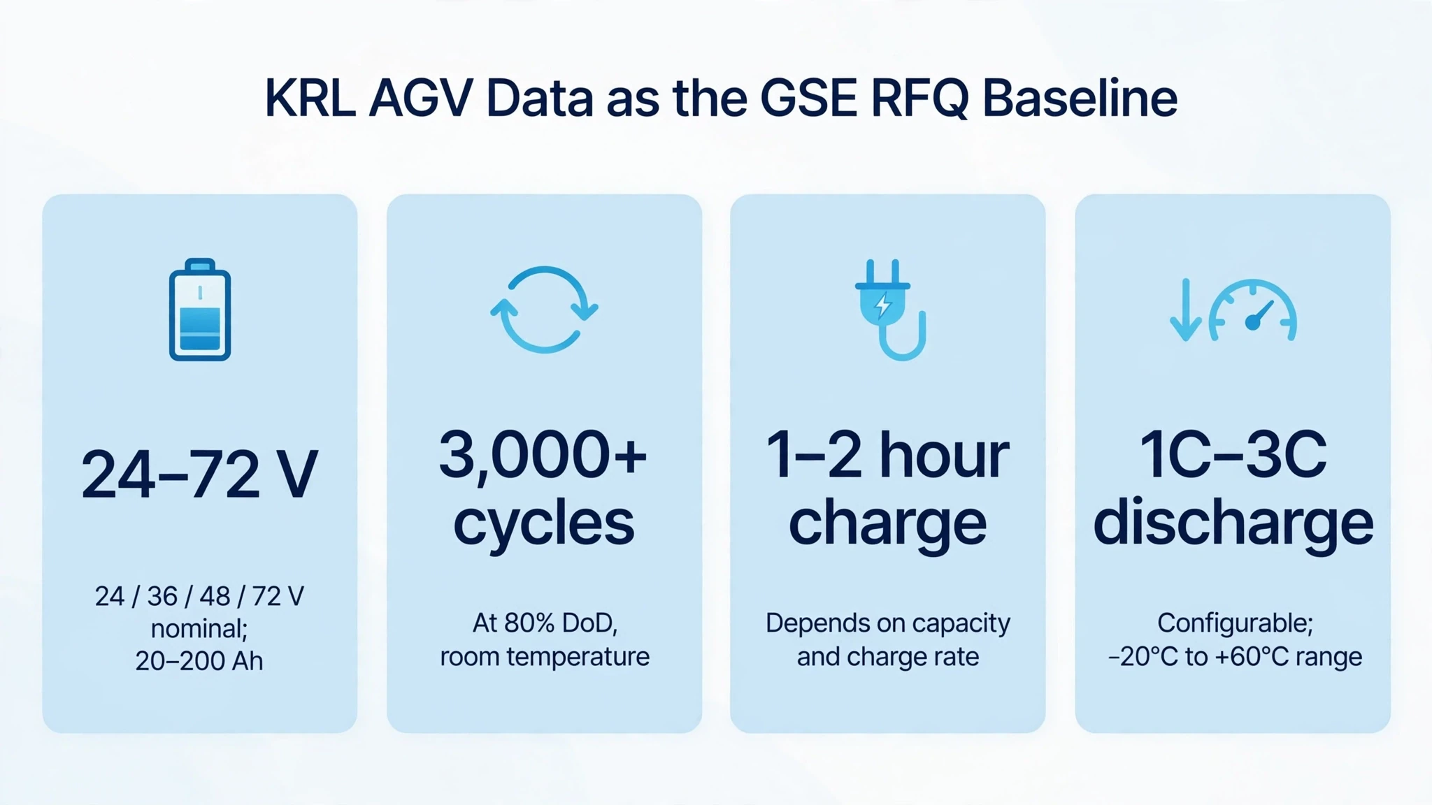
KRL's published AGV data as an RFQ baseline
| Parameter | Published typical/customizable KRL range | How to use it in a GSE project |
|---|---|---|
| Nominal voltage | 24V / 36V / 48V / 72V | Match the motor controller and auxiliary loads; request engineering review for other platforms |
| Capacity | 20Ah to 200Ah, with higher capacity customization | Size from measured energy use, reserve, temperature and aging allowance |
| Cycle life | At least 3,000 cycles at 80% DoD and room temperature | Verify the rating for the selected cell configuration |
| Charging time | 1 to 2 hours, depending on capacity and charge rate | Build the shift model from the project charge curve and available supply |
| Discharge rate | 1C to 3C, configurable | Check continuous and peak current against traction and hydraulic loads |
| Published operating range | -20°C to +60°C | Define separate charge, discharge and storage limits for the final design |
| BMS protection | Overcharge, over-discharge, overcurrent, short circuit and temperature | Map each protection event to the vehicle response and service procedure |
| Communication | RS485 and CAN customization; UART on selected packs | Supply the host protocol and message requirements during design |
| Environmental options | Self-heating and enclosure sealing up to IP67 on suitable custom projects | List the required heating and IP target in the RFQ |
Source: KRL AGV lithium battery specifications and customization options and KRL robot battery solutions.
Matching the power system to the GSE vehicle
Logged current, route, payload, shift duration and charging windows determine the final configuration. Two tractors with the same nominal voltage can need different batteries when one makes short baggage runs and the other pulls cargo dollies across a large hub.
Baggage tow tractors
An electric baggage tractor power unit must support repeated starts under drawbar load, predictable SOC reporting and enough usable energy for the assigned shift. The design review should capture the number of carts, route grade, travel distance, idle time and seasonal temperature.
The battery bay sets the mechanical limits. Record its length, width and height, then add the hold-down features, connector location and original battery mass. The vehicle manufacturer or responsible engineer should confirm the required weight distribution and tow rating after conversion.
Belt loaders and cargo loaders
A belt loader combines traction and conveyor demand. A cargo loader adds hydraulic pumps, repeated lift cycles and auxiliary control loads. Average energy alone can hide the current spike that occurs when the lift starts under payload.
Use logged continuous and peak current to select the cells, busbars, contactors and BMS current rating. Match the selected discharge rating to the duration and frequency of the logged traction and hydraulic peaks.
Aircraft tugs and pushback tractors
Treat a pushback tractor as a separate powertrain class. Aircraft mass, towbar or towbarless architecture, duty cycle, braking system and safety functions shape the complete power profile.
An aircraft tug lithium battery pack often calls for higher voltage, more stored energy and stronger thermal control than the published AGV range. KRL begins its feasibility review with the full traction profile, braking architecture and vehicle safety requirements.
| GSE type | Data that drives sizing | Main integration focus |
|---|---|---|
| Baggage tow tractor | Cart count, drawbar load, route, shift hours, charge windows | Battery mass, axle loading, controller interface and SOC visibility |
| Belt loader | Drive cycle, conveyor current, working height and idle time | Combined traction and conveyor peaks, cable routing and weather sealing |
| Cargo loader | Lift cycles, payload, hydraulic pump current and dwell time | Peak current duration, thermal control and stable voltage under lift load |
| Aircraft tug | Aircraft class, tow force, speed profile, grade and braking architecture | High-power validation, system safety, cooling and vehicle-level approval |
KRL can use these inputs to evaluate a custom battery pack and BMS configuration for mobile industrial equipment, including non-standard dimensions, interfaces and communication options.
Engineering for heat, cold, water and ramp vibration
Write the environmental limits as testable requirements before the team freezes the enclosure and connector design. Those requirements should cover temperature, ingress protection, vibration, mechanical loads, chemical exposure and the washdown method.
Set separate thermal limits for charging and discharge
KRL publishes a -20°C to +60°C operating range for its AGV platform and offers self-heating configurations for cold applications. The final data sheet should separate charging, discharging and storage limits. Those limits can differ, and the BMS must enforce the selected cell manufacturer's charge rules.
For a cold-weather fleet, define the lowest soak temperature, available preheat time and energy source for heating. A self-heating design can raise cell temperature before high-current charging. For a hot-weather fleet, define solar exposure, pavement temperature, duty cycle and parking conditions so the engineer can size heat paths and protection thresholds.
Seal the enclosure without trapping heat or pressure
Ingress protection depends on the complete enclosure. Cable glands, connector seals, service covers, pressure equalization and fastener torque all affect the result. KRL states that custom heavy-duty robot packs can use enclosures up to IP67. A GSE project should request an IP target and test evidence for its exact build.
The battery bay also needs a service plan. Technicians must reach fuses, disconnects and diagnostic ports without disturbing sealed joints that the maintenance procedure does not ask them to open.
Validate mounts against the actual route
Repeated low-level vibration and occasional shocks load the modules, busbars, connectors and enclosure mounts in different ways. Specify the vehicle's mounting orientation and route conditions. KRL's testing page lists vibration and compression evaluation, drop testing, thermal cycling, humidity exposure and IP/immersion testing among its in-house capabilities. Confirm which tests, standards and equipment apply to the proposed GSE pack. The validation plan should state the test standard, axis, level, duration and pass criteria for the GSE configuration.
Design interfaces that prevent connection errors
Keyed connectors, clear labels, protected terminals and defined cable support reduce installation and service errors. The high-voltage or high-current path needs a service disconnect and coordinated protection. The low-voltage side needs stable power, wake logic and an agreed response to lost communication.
These interfaces, control rules and mounting details give installers a reproducible GSE powertrain retrofit kit. KRL evaluates the pack and BMS. The integration plan covers vehicle-side wiring, controls, display and charger.
Lead-acid replacement, separate components or a custom assembly?
Lead-acid replacement preserves the current architecture. Teams with their own integration resources may prefer separate components. A KRL custom battery assembly puts the pack, enclosure, BMS and interfaces in one engineering scope, which reduces handoffs before the first vehicle reaches the workshop.
| Decision factor | Lead-acid replacement | Separate-component lithium retrofit | KRL custom-engineered battery assembly |
|---|---|---|---|
| Supply scope | Battery and existing charging workflow | Battery plus components selected by the integrator | Custom pack, BMS, enclosure and project-matched interfaces; charger options available |
| Mechanical fit | Uses the original tray format | Integrator adapts pack and mounting | KRL designs pack dimensions and interfaces from vehicle drawings |
| Charging | Existing lead-acid charger and service process | Integrator selects and validates charger | Charge rate and charger can be matched to the project |
| Vehicle data | Limited or added through separate devices | Integrator maps BMS and display | CAN or RS485 can be customized from an agreed protocol |
| Temperature strategy | Battery-specific maintenance and derating | Depends on selected pack | Wide-temperature and self-heating options can enter the custom design |
| Validation ownership | Fleet follows original equipment process | Integrator coordinates several suppliers | The project contract assigns pack tests and interface acceptance criteria among KRL, the customer and the vehicle integrator |
| Best fit | Fleets retaining the original architecture | Teams with vehicle integration resources | OEMs and contractors that want one battery engineering partner |
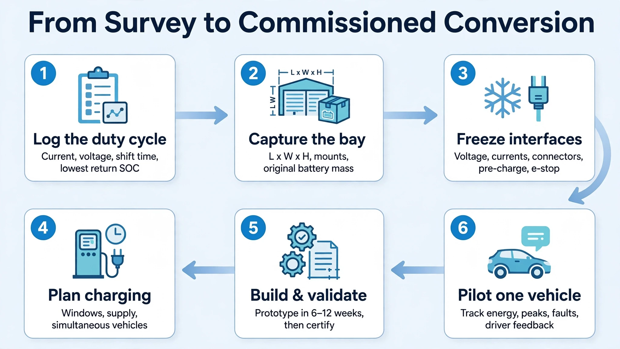
From vehicle survey to a commissioned conversion
A lead-acid-to-lithium baggage tractor conversion needs field data before pack design and a controlled pilot before fleet rollout. Engineers can shorten the installation window by resolving the fit, connectors, software and commissioning checks before the pack reaches the vehicle.
Step 1: Record the duty cycle
Log current, voltage and operating time across representative shifts. Mark towing, acceleration, grade, idle and auxiliary-load periods. Record the lowest return SOC and the time available for charging. Include hot and cold seasons when the fleet operates across a wide climate range.
Step 2: Capture the mechanical envelope
Provide a dimensioned battery-bay drawing, photographs, mounting details, lid clearance, cable exits and lifting restrictions. Record the original battery weight and center-of-mass location. Identify corrosion, damaged mounts or vehicle-to-vehicle variation before production begins.
Step 3: Freeze the electrical interfaces
Confirm nominal voltage, controller voltage limits, continuous current, peak current and auxiliary supplies. List connector part numbers, polarity, pre-charge needs, contactor logic, key switch behavior and emergency disconnect requirements.
Step 4: Define charging around the operation
Map parking locations, available AC supply, shift gaps and the number of vehicles that may charge at once. Size each window from logged energy use, required departure SOC and the approved charge curve.
Required nominal energy = measured shift energy / target usable fraction + operating reserve
KRL's published 1 to 2 hour charge range provides an RFQ baseline; the production schedule follows the selected pack and charger. Confirm distribution capacity, protection, connector placement and emergency procedures before fleet rollout. IATA identifies infrastructure, ramp operations, safety and economics as connected parts of the eGSE transition.
Step 5: Build and validate the prototype
KRL quotes 6 to 12 weeks for a typical prototype stage before certification work and volume production. The full schedule also covers design approval, component lead time, vehicle integration and validation.
Factory tests should cover electrical performance, BMS protection, communication, insulation, thermal behavior and the agreed environmental profile. Vehicle tests should cover traction, braking interaction, loaded route performance, SOC accuracy, charging and fault handling.
Step 6: Pilot one vehicle before fleet rollout
Run the first vehicle on representative assignments. Track energy per shift, peak current, temperature, charge time, fault events and driver feedback. Freeze the installation instructions after the pilot meets its acceptance criteria, then repeat the approved process across the fleet.
Information KRL needs for an engineering review
| Input | What to provide |
|---|---|
| Vehicle | Manufacturer, model, year, equipment type and quantity |
| Existing battery | Chemistry, nominal voltage, rated capacity, mass and charger |
| Battery bay | L x W x H drawing, mounting points, clearances and connector position |
| Electrical load | Continuous current, peak current, peak duration and controller limits |
| Operation | Payload, route, shift hours, idle time and seasonal conditions |
| Charging | Available supply, parking location, charge windows and simultaneous vehicles |
| Communication | CAN, RS485, UART or proprietary protocol documents |
| Environment | Minimum and maximum temperature, rain, washdown, dust and chemical exposure |
| Compliance | Destination market, transport route, applicable vehicle rules and requested standards |
Send KRL the vehicle data above for a custom battery and interface review.
Match certificates to the delivered configuration
An airport project has separate requirements for transport, battery safety, EMC, vehicle integration and operation. Keep the approved drawing, data sheet, BMS specification, UN 38.3 test summary and agreed validation reports with the delivered pack.
UN 38.3 covers transport testing for the cell or battery type being shipped. IEC 62619:2022 addresses industrial lithium battery safety for non-road motive applications such as forklifts and AGVs. UL 2580 includes GSE in its scope, while CE marking follows the EU legislation applicable to the finished product.
KRL's AGV page lists UL, CE, UN 38.3 and IEC among its certification standards. Name the exact standard and evidence required for the ordered configuration in the RFQ.
EASA's adopted ground-handling framework, scheduled to apply from 27 March 2028, will require operators to keep GSE serviceable, use it within its design parameters, inspect it before first use or seasonal operation and maintain it under a defined program. Add the supplier's installation, inspection, storage and maintenance instructions to that program.
Building the business case for GSE electrification
Build the business case from fleet records. Count the costs and operating constraints the conversion can change, then compare them with the installed system cost and infrastructure plan.
IATA's CO2 and noise figures help frame the environmental case. The operating case comes from local data:
- Fuel or electricity consumed by each vehicle class
- Lead-acid watering, equalization, battery-change and room-maintenance labor
- Diesel engine, transmission, exhaust and fluid service
- Charger losses, demand charges and infrastructure work
- Spare batteries and backup vehicles tied to the current schedule
- Unplanned downtime, roadside recovery and delayed assignment records
- Pack, charger, installation, training and financing cost
Use this equation:
Annual operating benefit = avoided fuel and maintenance cost + reduced battery-service labor + recovered vehicle availability - electricity and financing cost
Run sensitivity cases for operating hours, electricity price, battery life, maintenance cost and utilization. Present environmental targets beside the measured operating case.
KRL rates its published AGV platform for at least 3,000 cycles at 80% DoD and room temperature. Use the selected pack's rated cycle life in the model, then test temperature, DoD, charge rate and calendar aging as sensitivity factors.
FAQ
Can a GSE fleet use opportunity charging?
Can KRL support cold-weather airport operation?
Does KRL support CAN 2.0B or J1939?
Can the system include an on-board charger and dashboard display?
Which certifications apply to a GSE lithium conversion?
Start with the vehicle, shift and battery compartment
Send KRL your vehicle model, battery-bay drawing, voltage and current data, shift profile, charging supply and communication protocol. Its engineers will use those inputs to develop the pack architecture, capacity, enclosure, BMS, thermal options and charger proposal for your airport GSE lithium power system.
Explore KRL's custom AGV and industrial vehicle lithium battery systems or request a GSE engineering review. The contact page lists a 24-hour expert response.
Technical sources
- KRL AGV Battery Solutions
- KRL Robot Battery Solutions
- KRL Power company and engineering capabilities
- KRL testing and certification capabilities
- IATA Electric GSE guidance and impact data
- OSHA industrial battery charging guidance
- EU ground-handling framework and application date
- IEC 62619:2022 scope
- UL 2580 overview
- UN Manual of Tests and Criteria