

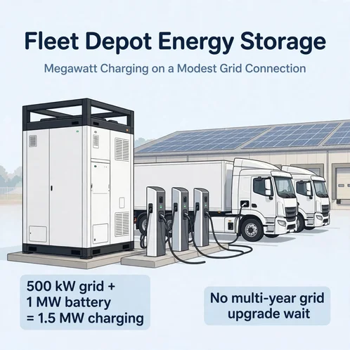
Procuring twenty heavy-duty electric freight trucks or municipal transit buses is often faster than securing the utility grid power needed to charge them.
When logistics operators transition forty-ton semi-trucks (Class 8 e-trucks or European eHGVs) and transit buses to electric drivetrains, depot power requirements jump from kilowatts to multiple megawatts.
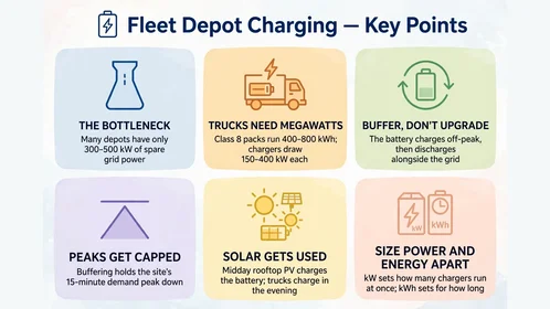
However, existing distribution centers and municipal bus garages frequently sit on constrained utility feeders with only 350kVA to 600kVA of spare transformer apparent power (apparent power), which yields roughly 300kW to 500kW of usable active power (active power = apparent power × power factor) depending on site power factor.
Applying to the local utility for a multi-megawatt substation upgrade often triggers multi-year interconnection queues and high trenching and transformer costs.
Deploying a fleet depot energy storage system behind the meter solves this bottleneck by acting as an on-site power buffer and energy reservoir.
By charging from a modest existing grid connection (and warehouse rooftop solar PV) during off-peak hours, a containerized battery system discharges megawatt-level AC power alongside the grid when the fleet returns for fast turnaround charging.
1. The Megawatt Grid Bottleneck: Why Heavy-Duty Truck & Bus Depots Cannot Rely on the Grid Alone
1.1 Passenger EV charging versus heavy-duty commercial electric truck charging BESS demands
Designing a commercial electric truck charging bess requires accounting for vehicle battery capacities and turnaround schedules that differ sharply from passenger cars:
- Passenger electric vehicles: Typically carry 60kWh to 80kWh battery packs and can charge slowly at 7kW to 22kW over ten hours.
- Heavy-duty electric trucks (Class 8 / 40-ton eHGVs): Commonly carry traction batteries in the 400kWh to 800kWh reference range, varying by vehicle model, axle configuration, and regional or long-haul duty cycle.
- Municipal transit and double-decker buses: Typically use 300kWh to 550kWh battery packs as an industry reference range, recharging within overnight depot windows or route layovers.
- High-power dispenser standards: Meeting 45-minute driver rest windows or tight shift schedules requires Combined Charging System (CCS) DC fast chargers (commonly rated from 150kW to 400kW) or emerging Megawatt Charging System (MCS) dispensers engineered for higher-power heavy-duty applications.
1.2 Three operational barriers: Solving the eHGV bus depot grid capacity constraint
Fleet directors and charge point operators (CPOs) face three structural barriers when electrifying a logistics hub or transit garage.
Overcoming an ehgv bus depot grid capacity constraint requires addressing:
-
Utility feeder capacity ceilings (kVA versus kW):
Utility transformers are rated in apparent power (kVA), while active charging power is measured in kilowatts (kW = kVA × power factor). Many industrial logistics parks and urban bus depots have less than 500kW of spare active power import capacity. Starting even two 300kW DC fast chargers simultaneously without local buffering or active load management can exceed remaining feeder capacity and trigger upstream overcurrent protection. -
Punitive monthly peak demand charges:
When ten or fifteen electric trucks plug in together at 18:00 after daytime delivery routes, site power draw spikes into the multi-megawatt range. Under commercial tariff structures that bill peak fifteen-minute demand ($/kW or $/kVA), unbuffered fleet charging inflates monthly utility bills and erodes fuel savings. -
Day-night mismatch with warehouse rooftop solar PV:
Logistics distribution centers feature large roof areas suitable for 500kWp to 2MWp solar arrays. Yet solar generation peaks at midday while delivery trucks are out on the road, and vehicles return for charging in the evening after solar output drops to zero.
Facing transformer capacity limits or multi-year DNO connection queues in European or UK logistics hubs? Read our regional guide on commercial battery storage for business in Europe and the UK.
2. Inside a Megawatt Charging Hub Battery System: AC-Coupled versus Shared DC-Bus Architectures
2.1 How a battery buffered DC fast charging depot multiplies available grid power
A battery buffered dc fast charging depot decouples peak vehicle charging power from the utility active power import limit.
Consider an illustrative logistics depot with a 500kW utility active power cap (derived from transformer kVA rating and power factor) and a 100kW constant warehouse base load, leaving 400kW of net grid power available for charging and battery recovery:
- Off-peak recharging: While trucks are out on delivery routes, the energy management system (EMS) uses the remaining 400kW net grid capacity (plus midday rooftop solar power) to recharge a 1MW / 2MWh containerized battery.
- Recharge duration verification: Dividing 2,000 kWh by 400 kW yields a 5-hour theoretical minimum under zero-loss conditions. In practice, recharging takes longer after accounting for AC-to-DC conversion losses, liquid-cooling auxiliary loads, high-SOC current tapering, and solar variability.
- EMS recovery scheduling: The depot EMS must schedule recovery charging based on the next fleet arrival window, available net recharge power, and expected discharge depth.
- Peak co-discharging: When four 300kW trucks connect simultaneously (1,200kW charger demand), the net grid supplies 400kW while the BESS discharges 800kW. Provided the BESS Power Conversion System (PCS) rating and main AC distribution busbars are sized for the combined current, the depot delivers 1,200kW without breaching the utility transformer limit.
2.2 Comparing AC-coupled and shared common DC-bus topologies
When engineering a megawatt charging hub battery system, EPC contractors evaluate two primary electrical coupling architectures.
| Architecture | Grid and distribution route | Battery, solar and charger connections |
|---|---|---|
| AC-coupled depot — standard KRL-B2M6L integration | Utility grid feed → main 400 V AC switchboard → warehouse base loads and AC/DC charger rectifiers → CCS/MCS DC fast chargers | KRL containerized BESS ↔ 400 Vac bidirectional PCS ↔ main AC switchboard |
| EPC shared common DC bus — custom DC integration | Utility grid feed ↔ bidirectional AC/DC PCS with pre-charge and bus protection ↔ regulated high-voltage DC bus | LiFePO4 battery racks ↔ isolated DC/DC; rooftop PV array → solar PV MPPT; remote fleet dispensers ↔ isolated DC/DC stage; all connect to the regulated DC bus |
- Architecture A (AC-Coupled 400Vac Bus Topology, Standard KRL Configuration):
- Configuration: The containerized BESS (such as the KRL-B2M6L series, which features a 400Vac on-grid/off-grid output, 750kW or 1MW PCS, and integrated PV DC input) connects directly to the depot's 400V AC switchboard alongside standalone AC-input DC fast chargers.
- Best use case: Standard commercial installations and depot retrofits where compatibility with any third-party CCS or MCS charger brand is required.
- Trade-off: Battery and solar energy pass through DC/AC inversion in the PCS and AC/DC rectification inside the external charging cabinets.
- Architecture B (EPC Shared Common DC-Bus Topology):
- Configuration: In specialized EPC system-integration projects, battery racks, solar MPPT stages, and remote charging dispensers can be engineered around a common high-voltage DC bus (often discussed in the 750V to 1000V DC industry range).
- Engineering requirements: Connecting battery strings, PV converters, and fast-charging dispensers onto a shared DC bus requires isolated DC/DC conversion stages, high-speed DC bus protection, pre-charge circuits, and strict voltage-window matching.
- Note on KRL specifications: Because standard KRL-B2M6L containers output 400Vac via integrated PCS units rather than a native external MCS DC bus port, shared DC-bus projects require custom OEM/EPC interface engineering.
2.3 Table 1: Comparison of fleet depot charging infrastructure options
| Evaluation Parameter | Grid Upgrade + Direct Chargers | Small Cabinet Buffering (100–261kWh) | KRL Megawatt Containerized BESS (750kW–2MW+) |
|---|---|---|---|
| Required Utility Grid Import | Multi-MW dedicated feeder (2MW to 5MW+) | Low to moderate (50kW to 250kW active power) | Uses existing 300kW to 800kW active grid limit |
| Project Implementation Scope | Utility substation & trenching approval | Single cabinet + local sub-panel wiring | Modular 20ft container + site civil/grid works |
| Supported Fleet Scale | Large fleets (after utility upgrade completes) | 1 to 3 light/medium commercial vans or 1 bus | Heavy Class 8 e-trucks and multi-bus depots |
| Peak Demand Charge Control | None (full exposure to MW charging spikes) | Buffers single-charger demand peaks | Caps depot-wide utility kW and kVA peak draw |
Engineering boundary note:
- Actual site commissioning timelines depend on local network operator approvals, civil foundation works, and switchgear installation rather than battery manufacturing time alone.
- A battery-buffered charging system mitigates multi-hour charging peaks when total 24-hour energy consumption (kWh) fits within the 24-hour energy import capacity of the existing grid feeder plus on-site solar generation.
Exploring modular cabinets and multi-megawatt containers for commercial charging infrastructure? Review KRL Power's full range of commercial and industrial (C&I) energy storage systems.
Share the transformer kVA rating, site power factor, base load and charging arrival schedule with KRL Power. You will receive a review of the required battery kW, battery kWh and available recharge window.
3. Engineering Sizing Methodology: How to Size a BESS for a Truck or Bus Depot
Sizing a stationary storage buffer requires calculating rated power (kW) and usable energy capacity (kWh) under a unified load scenario and a consistent electrical metering boundary.
3.1 Defining the metering boundary and transformer active power limit
Before subtracting grid energy from vehicle charging demand, engineers must align all power and energy figures to the 400V AC distribution bus (Point of Common Coupling):
-
Transformer active power limit (grid import limit): Convert utility transformer apparent power (transformer apparent-power rating in kVA) to active power using site power factor:
grid import limit (kW) = transformer apparent-power rating (kVA) × power factor
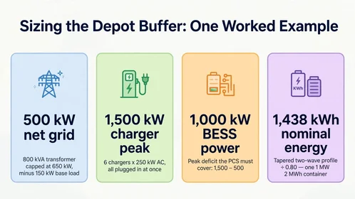
For example, an 800kVA transformer operating at power factor = 0.90 with a safety margin provides a capped active import limit of grid import limit = 650 kW. -
Net grid power available for the charging bus (net grid power): Subtract continuous warehouse base loads (facility base load = 150 kW) from the grid cap:
net grid power = 650 kW - 150 kW = 500 kW - Charger AC input versus vehicle DC battery energy: Because DC fast chargers incur internal AC-to-DC conversion and cable losses (charger efficiency ≈ 0.94), delivering 188 kWh of DC energy into a truck battery requires 200 kWh of AC input energy at the 400V AC bus. All bus-level calculations below use AC bus kWh.
3.2 Step 1: Calculate the peak AC power deficit (kW)
Determine the maximum simultaneous AC power drawn by the chargers when a wave of trucks plugs in at low state of charge (SOC) and subtract the available net grid power:
required BESS AC power (kW) = ( number of chargers × peak AC input per charger × simultaneity factor ) - net grid power
Unified depot sizing scenario (Power calculation):
- The depot operates 6 DC fast chargers, each drawing 250kW of peak AC input power (peak AC input per charger).
- At the start of a charging wave, 6 low-SOC trucks plug in simultaneously (simultaneity factor = 1.0), creating a peak AC charging demand of 6 × 250 kW = 1,500 kW (plus 150kW warehouse base load = 1,650kW total site demand).
-
With net grid power = 500 kW available from the utility feeder for charging, the BESS PCS must supply a peak AC output of:
required BESS AC power = 1,500 kW - 500 kW = 1,000 kW (1.0MW)
3.3 Step 2: Calculate the nominal DC battery energy capacity (kWh)
Next, calculate the required nominal DC battery capacity (nominal battery DC energy) for that exact same 6-charger depot across two operating profiles (tapered real-world charging versus continuous full-power charging) over a charging window = 2.5 hour evening window with zero evening solar (solar AC energy = 0):
nominal battery DC energy (kWh) = (charger AC energy during the window - ( net grid power × charging window )) ÷ (DoD × BESS discharge efficiency)
Where charger AC energy during the window is the total AC energy consumed by the chargers, DoD is usable depth of discharge, and BESS discharge efficiency accounts for BESS DC-to-AC discharge conversion and auxiliary cooling losses (combined DoD × BESS discharge efficiency = 0.80).
- Profile A (Tapered charging curve across 12 trucks in two staggered waves):
- Six trucks charge in Wave 1 and six trucks charge in Wave 2 over the 2.5-hour window (12 trucks total). Each truck draws 200 kWh at the AC charger input (≈ 188 kWh stored in the vehicle battery), totaling charger AC energy during the window = 12 × 200 kWh = 2,400 kWh.
- Why average power differs from peak power: Although the 6 chargers hit 1,500 kW peak when low-SOC trucks first connect (requiring the 1,000 kW PCS sized in Step 1), vehicle BMS charging curves taper power as truck SOC rises above 70%, resulting in an average AC charging load of 2,400 kWh ÷ 2.5 h = 960 kW across the window.
- Net grid AC energy supplied over 2.5 hours: 500 kW × 2.5 h = 1,250 kWh.
- Required BESS AC output energy: 2,400 kWh - 1,250 kWh = 1,150 kWh.
- Required BESS DC nominal capacity: 1,150 kWh ÷ 0.80 = 1,438 kWh, which is met by a single 1MW / 2MWh KRL-B2M6L container.
- Profile B (Continuous 1,500kW full-load stress case for 2.5 hours):
- If continuous back-to-back low-SOC truck arrivals keep all 6 chargers running at their full 1,500 kW AC rating for the entire 2.5 hours without tapering, total AC charger demand reaches 1,500 kW × 2.5 h = 3,750 kWh.
- Subtracting 1,250 kWh of net grid AC supply leaves 1,000 kW × 2.5 h = 2,500 kWh of AC energy that the BESS must deliver.
- Dividing 2,500 kWh by 0.80 requires 3,125 kWh (3.125MWh) of nominal DC battery capacity, requiring a multi-container parallel configuration.
3.4 Step 3: Verify off-peak recharge recovery time
Finally, verify that the available net grid power (net grid power = 500 kW) and daytime rooftop solar PV can replenish the stationary battery before the next fleet arrival wave:
- In Profile A, restoring 1,150 kWh of discharged AC energy at an overall round-trip AC-DC-AC efficiency of ≈ 85% requires approximately 1,353 kWh of AC recharge input.
- At 500 kW net grid import, recharging takes a theoretical minimum of 1,353 kWh ÷ 500 kW ≈ 2.7 hours, or roughly 3.2 to 3.5 hours after accounting for high-SOC current tapering and auxiliary cooling loads.
4. KRL Power Product Selection Matrix for Fleet Charging Depots
A foundational rule in depot engineering is separating power from energy: the BESS rated power (kW) determines how many fast chargers can run simultaneously, while the nominal energy capacity (kWh) determines how many hours that charging load can be sustained. Both parameters must be verified independently.
4.1 Table 2: KRL Power BESS selection guide by fleet depot scale
| Fleet Depot Scenario | Recommended KRL Model | Rated Power & Capacity | Engineering Selection Basis |
|---|---|---|---|
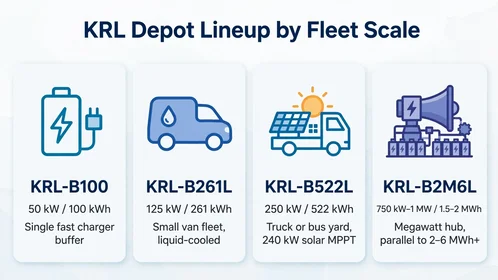
| Single or small commercial EV group | KRL-B100 | 50kW / 100kWh | Adds up to 50kW AC buffer for single fast charger and solar self-consumption |
| Small regional delivery van fleet | KRL-B261L | 125kW / 261kWh | Adds up to 125kW AC buffer alongside grid; liquid-cooled (≤3°C delta, IP65 battery) |
| Regional truck or municipal bus yard | KRL-B522L | 250kW / 522kWh | Adds up to 250kW AC buffer alongside grid; includes 240kW / 2-input solar MPPT |
| Multi-truck simultaneous fast charging | KRL-B2M6L (750kW / 1.5MWh) | 750kW / 1.5MWh | High energy buffer; verify that peak BESS kW deficit stays ≤750kW |
| Megawatt fleet charging hub | KRL-B2M6L (1MW / 2MWh) | 1.0MW / 2.0MWh | Matches the 1MW peak power deficit and 1.44MWh tapered energy model in Section 3 |
| Large-scale logistics & port terminals | Multi-unit KRL-B2M6L Parallel | 1–2MW / 2–6MWh+ | Parallel containers sized for continuous multi-MWh fleet energy demand |
4.2 Containerized and cabinet hardware highlights
KRL Power manufactures liquid-cooled cabinets and containers built around automotive-grade LiFePO4 battery technology:
- Megawatt container platforms: The KRL-B2M6L containerized BESS series offers standard catalog ratings of 750kW / 1.5MWh and 1.0MW / 2.0MWh (400Vac output), alongside 1.2MW / 2.6MWh configurations and multi-container parallel scaling.
- Outage backup boundaries: During utility blackouts, the B2M6L sub-10ms switching and grid-forming PCS can sustain designated critical charging loads within the PCS kW limit and available battery SOC, provided proper load-shedding and anti-islanding protection interlocks are installed.
- Thermal and fire safety: Closed-loop liquid cooling and integrated fire-suppression interfaces support safe depot operation.
- Modular C&I cabinets: For medium and compact depots, review the KRL-B522L (250kW / 522kWh) liquid-cooled storage system, the KRL-B261L (125kW / 261kWh) liquid-cooled C&I ESS, and the KRL-B100 (50kW / 100kWh) BESS cabinet.
Modeling capital expenditure, demand-charge savings, and simple payback for a fleet charging project? Consult our step-by-step commercial battery storage cost and ROI guide.
5. Request a Depot Grid-Constraint Sizing Evaluation
Electrifying heavy commercial trucks and municipal bus fleets does not need to stall behind multi-year utility substation upgrades or punitive monthly peak demand charges.
Deploying a modular liquid-cooled cabinet or containerized fleet depot energy storage system turns an existing modest grid connection and warehouse solar roof into a high-power charging hub.
- For fleet operations directors, transit planners, and CPOs: Share your depot's existing utility transformer rating (kVA), power factor, warehouse base load (kW), number of vehicles, battery capacities (kWh), and daily route arrival/departure schedules with KRL Power's engineering team.
- Request a custom depot sizing model, single-line diagram (SLD) review, and EXW/FOB/CIF project quotation from KRL Power's megawatt storage engineering team within 48 hours.
FAQ
How does a battery-buffered charging system bypass utility grid upgrades for fleet depots?
The depot energy management system caps utility import within the transformer's safe active power limit, recharging the battery during off-peak hours or from midday rooftop solar PV. When vehicles plug in simultaneously, the battery discharges AC power alongside the grid feed to deliver full megawatt-level charging power without exceeding the utility transformer rating.
What is the difference between AC-coupled and DC-coupled fleet charging hubs?
In an EPC-integrated shared common DC-bus hub, battery racks, solar MPPT modules, and isolated DC-to-DC charging dispensers connect on a regulated high-voltage DC bus equipped with pre-charge and DC protection gear, reducing intermediate AC/DC conversion stages.
Can a depot BESS keep electric trucks and buses charging during a power outage?
Systems equipped with a grid-forming bidirectional PCS and an automatic isolation switch (such as the KRL-B2M6L series) can disconnect from a failed utility grid in under 10 milliseconds and establish an islanded AC microgrid. With load-shedding controls that restrict active chargers to match PCS kW limits and remaining battery SOC, critical fleet vehicles can continue charging during blackouts.