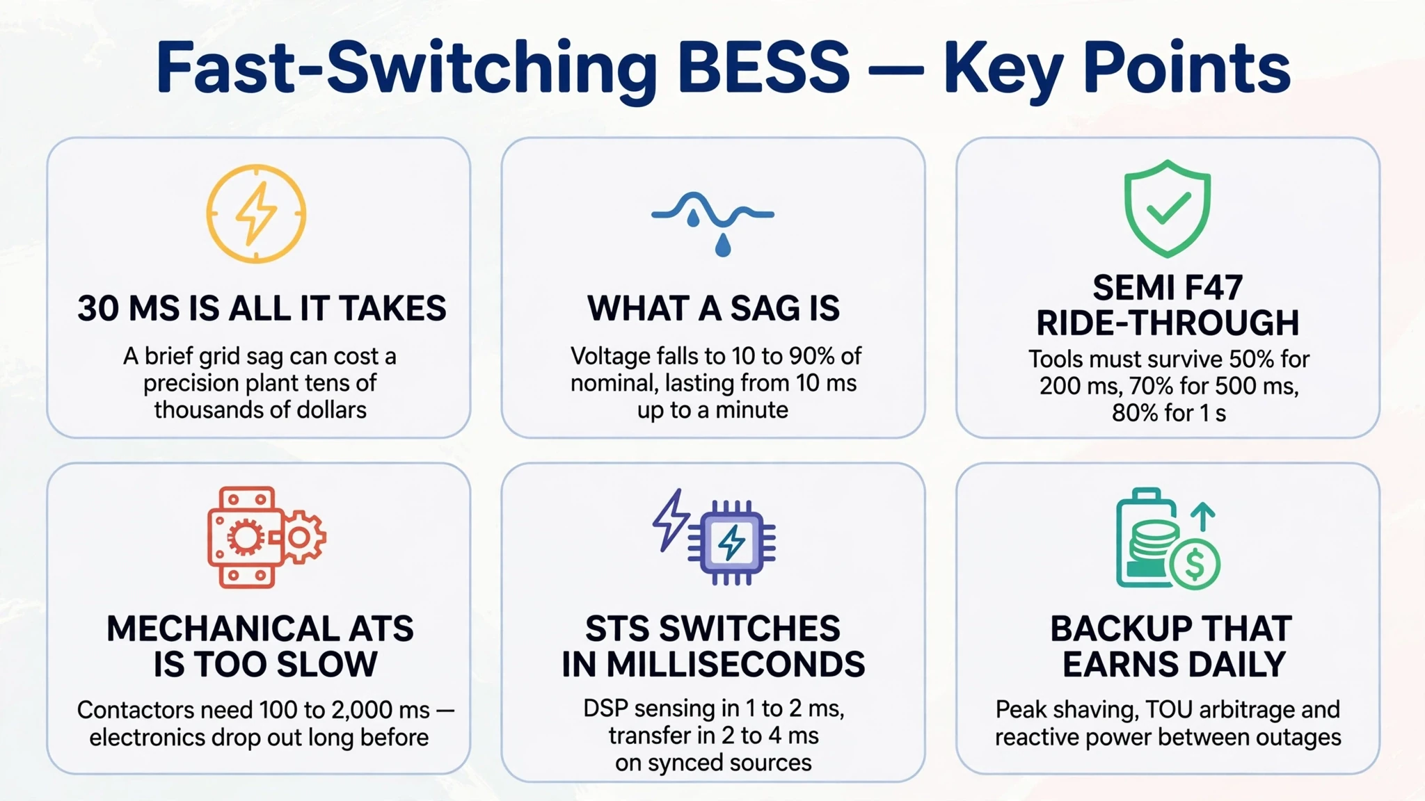
A utility grid disturbance lasting thirty milliseconds often costs a semiconductor foundry or precision machine shop tens of thousands of dollars.
When grid voltage sags during a lightning strike or substation breaker reclosure, sensitive variable frequency drives trip on DC-bus under-voltage. High-speed computer numerical control (CNC) machine tool spindles lose position synchronization, snapping solid-carbide cutting heads and gouging expensive titanium airframe components.
Cleanroom air-handling fans, turbo-molecular vacuum pumps and surface-mount technology (SMT) pick-and-place lines reset, forcing entire production batches to be scrapped.
Deploying an sts integrated bess cabinet or fast-switching energy storage system isolates critical plant buses from severe grid anomalies. Standard KRL commercial BESS cabinets deliver sub-ten-millisecond (<10ms) transfer. Specialized high-speed static transfer switch (STS) engineering options support dedicated dual-source industrial lines.
Unlike traditional emergency diesel generators and standby lead-acid uninterruptible power supplies, a factory-integrated battery energy storage system acts as an active financial asset. It performs daily tariff arbitrage, shaves peak demand charges, absorbs motor regenerative braking energy when paired with regenerative drives, and protects critical manufacturing tools.
1. The Multi-Million-Dollar Disturbance: Why Voltage Sags Disrupt Precision Facilities
1.1 Anatomy of an industrial voltage sag
Across automated industrial facilities, short-duration voltage sags represent one of the most frequent and costly power quality disruptions.
A voltage sag (or dip) is a sudden reduction in root-mean-square (RMS) AC voltage between ten percent and ninety percent of nominal rating, lasting from half a cycle (ten milliseconds at 50Hz) up to one minute.
Common causes include:
- Transmission-level lightning strikes that clear through utility reclosers
- Utility grid transformer tap-changing and capacitor bank switching
- Sudden high-inrush motor starts or short-circuit faults in neighboring industrial plants
- Transient weather events on exposed distribution feeders
Because utility automated reclosing cycles take between one hundred and three hundred milliseconds to clear feeder faults, unprotected factory machinery experiences immediate power disruption.
1.2 Operational damage across high-precision industrial sectors
Modern automated production tools rely on microprocessors, switched-mode power supplies, and digital servo amplifiers that tolerate minimal DC-link voltage deviation.
Key failure modes across industrial sectors include:
- Five-axis CNC machining centers: High-speed spindles operating at twenty thousand revolutions per minute lose field orientation when bus voltage drops below eighty percent. Axis feed motors stop abruptly while the spindle coasts, causing tool collisions, spindle bearing damage, and workpiece destruction.
- Semiconductor fabrication and packaging: Photolithography steppers, wire bonders, and chemical vapor deposition (CVD) tools abort process cycles. A five-cycle voltage dip can scrap an entire wafer lot and contaminate cleanroom high-vacuum chambers.
- SMT electronics assembly: Pick-and-place placement heads misalign, dropping micro-components. Solder reflow ovens experience thermal profile deviations that cause defective joints, requiring four to eight hours of line inspection and reset.
- Precision optical and medical molding: Multi-cavity injection molders stop mid-stroke, causing plastic to freeze in hot runner manifolds and requiring manual mold disassembly.
1.3 The SEMI F47 voltage sag immunity standard
To address power disturbance vulnerabilities in microelectronics manufacturing, the semiconductor industry established the SEMI F47 specification.
The SEMI F47 standard defines the minimum voltage sag ride-through capability that processing equipment must withstand without interrupting operations:
- Voltage sags down to fifty percent of nominal for two hundred milliseconds (0.2 seconds)
- Voltage sags down to seventy percent of nominal for five hundred milliseconds (0.5 seconds)
- Voltage sags down to eighty percent of nominal for one full second (1.0 second)
SEMI F47 is an equipment-level design standard rather than an electrical facility mandate. It specifies what individual semiconductor machines must tolerate on their internal DC power rails.
However, deep utility voltage sags that drop below fifty percent or persist beyond the standard duration still trigger factory-wide shutdowns.
Integrating fast-switching battery storage or an upstream STS provides a facility-level voltage buffer. It maintains nominal AC bus voltage before utility sags breach tool tolerance boundaries.
Facilities planning comprehensive power reliability can review factory specifications for KRL Power's modular commercial and industrial (C&I) energy storage systems to protect cleanrooms and heavy machinery.
2. Anatomy of Fast-Switching BESS & High-Speed STS Architectures
2.1 Mechanical ATS versus solid-state STS physical switching speeds
Industrial facilities traditionally rely on automatic transfer switches (ATS) to switch power between utility feeds and emergency sources.
A mechanical ATS uses motorized contactors or solenoid-driven mechanical linkages. Physical contact travel and arc-extinguishing mechanisms require one hundred to two thousand milliseconds to complete a transfer.
During this mechanical delay, sensitive digital electronics lose DC bus capacitance and trigger emergency shutdown faults.
A solid-state Static Transfer Switch (STS) replaces moving mechanical parts with high-power anti-parallel Silicon Controlled Rectifiers (SCR thyristors):
- Fast digital sensing: Digital signal processors (DSP) continuously monitor grid voltage RMS values and phase angles, detecting anomalies within one to two milliseconds.
- Natural commutation requirements: Unlike gate-turn-off devices such as IGBTs, standard SCR thyristors cannot be opened instantaneously via gate signals alone. They turn off only when conduction current crosses zero or through line-forced commutation.
- Dual-source synchronization: When two synchronized AC sources are available, the STS fires alternate thyristors to transfer load current within a fraction of an AC cycle (typically two to four milliseconds).
- Sub-cycle load transfer: Rapid commutation prevents voltage dropouts, keeping equipment DC-link capacitors charged and preventing servo fault trips.
2.2 Comparison of industrial power protection architectures
To evaluate capital expenditure, backup capabilities, and operating economics, facility engineers compare three main backup power architectures.
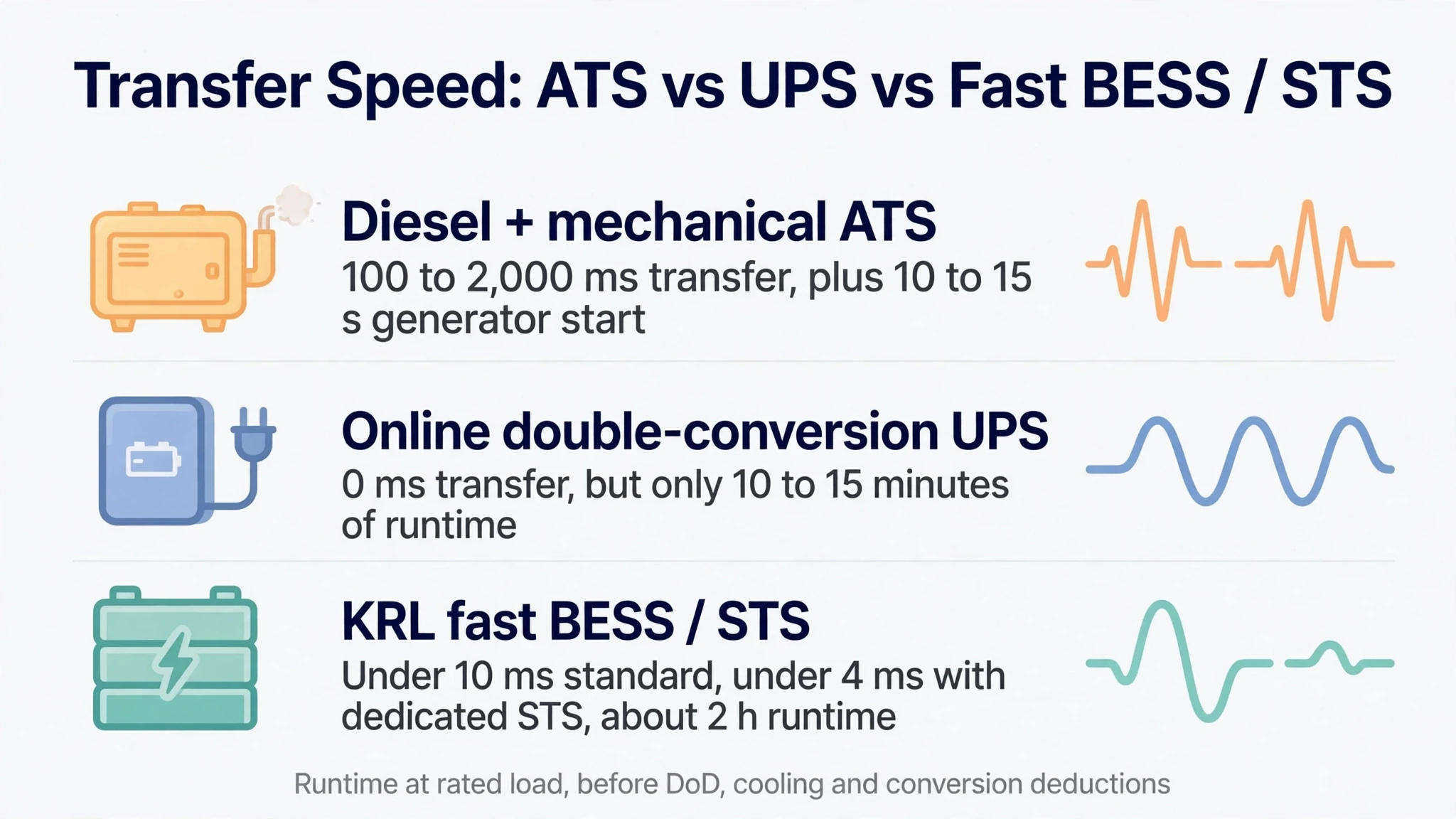
The table below contrasts mechanical ATS setups, traditional double-conversion UPS units, and KRL fast-switching BESS configurations.
| Evaluation Parameter | Diesel Generator + Mechanical ATS | Double-Conversion Online UPS | KRL Fast BESS / STS Architecture |
|---|---|---|---|
| Transfer Switching Duration | 100ms to 2,000ms (mechanical contactor) | 0ms (continuous double conversion) | <10ms standard BESS (<4ms with dedicated STS) |
| Backup Source Availability | 10 to 15 seconds (cold diesel engine start) | 0 seconds (inverter active online) | 0 seconds (active inverter or fast standby) |
| Runtime at 100% Rated Power | Hours to days (fuel supply dependent) | 10 to 15 minutes (orderly shutdown battery) | ~2 hours at rated load (scalable with capacity) |
| Operating Revenue & Efficiency | Zero (standby fuel burns and test costs) | Zero (steady conversion loss, ~95-97% efficiency) | Daily peak shaving, TOU arbitrage, power quality |
Engineering boundary note:
- Standard KRL commercial BESS cabinets deliver sub-ten-millisecond (<10ms) on-grid to off-grid switching.
- At rated power, the KRL-B100 (50kW / 100kWh) delivers approximately two hours of continuous full-load runtime, and the KRL-B261L (125kW / 261kWh) delivers approximately 2.1 hours.
- These runtimes are calculated before deducting depth-of-discharge limits, auxiliary cooling loads, and conversion losses.
- Extending backup to four or eight hours requires sizing for dedicated critical sub-panels or expanding storage capacity.
2.3 Grid-forming inverter controls on large-scale storage platforms
Fast static switching on microgrids requires an inverter capable of establishing an immediate, stable voltage reference without relying on grid voltage signals.
Standard grid-following inverters measure grid voltage angle to synchronize current injection. If the grid drops suddenly, a grid-following inverter loses its reference and shuts down on anti-islanding protection.
On large-scale platforms such as the KRL-B2M6L container series, KRL integrates grid-forming Power Conversion Systems (PCS) running Virtual Synchronous Generator (VSG) algorithms:
- 1. Emulated inertia: Digital control loops emulate the mechanical inertia and damping characteristics of a synchronous turbine generator.
- 2. Self-standing voltage source: The PCS maintains internal voltage amplitude and frequency setpoints, presenting a stiff AC voltage source to the plant bus.
- 3. Bumpless transition: When isolation devices disconnect the utility feed, the grid-forming system carries facility loads without phase angle jumps or voltage spikes.
- 4. Black-start capability: If complete utility blackout occurs, the grid-forming container can re-energize plant distribution transformers and motor circuits from a cold state.
3. Financial Transformation: Turning Sunk-Cost Backup into a 24/7 Profit Asset
3.1 Why traditional double-conversion UPS systems drain operating margins
For decades, precision manufacturers treated uninterruptible power systems as necessary insurance expenses that produced zero financial return.
A traditional double-conversion UPS rectifies incoming AC utility power into DC to float-charge batteries, then inverts DC back to AC for critical loads.
While modern high-efficiency double-conversion UPS units achieve ninety-four to ninety-seven percent efficiency under nominal loading, continuous operation still incurs steady penalties:
- Continuous conversion losses: Even at ninety-six percent efficiency, four percent of all critical-load electrical energy is lost around the clock as waste heat.
- Dedicated climate control: Air-conditioned battery rooms must run continuously to prevent lead-acid thermal degradation.
- Frequent cell replacement: Valve-regulated lead-acid (VRLA) batteries degrade rapidly under industrial temperatures, requiring complete cell pack replacement every three to five years.
- Zero demand management: Standard UPS installations cannot discharge stored energy to reduce utility demand charges or capture time-of-use tariff spreads.
3.2 Value stacking with an STS integrated BESS
A modern precision manufacturing backup power station replaces passive standby hardware with an active, revenue-generating energy asset.
Facility engineers stack four operational revenue streams to accelerate system payback:
- 1. Time-of-use (TOU) tariff arbitrage:
The energy management system charges the battery bank during low-cost overnight or midday solar hours, then discharges stored power during high-cost peak production shifts.
- 2. Contracted demand charge reduction (peak shaving):
Precision manufacturing plants pay substantial monthly demand charges based on their highest fifteen-minute power draw. The BESS discharges dynamically when multiple CNC machines, chillers, or air compressors start simultaneously, capping peak demand below contracted utility limits.
- 3. Dynamic power quality support:
The four-quadrant bidirectional PCS injects capacitive or inductive reactive power (kVAR) in milliseconds. Subject to the inverter apparent power (kVA) rating and current active load, this provides dynamic power factor correction and mitigates utility low-power-factor penalties.
- 4. Outage and sag ride-through:
When utility disturbances occur, the fast-switching BESS or STS maintains continuous bus voltage, preventing lost machine setups, broken tooling, and ruined material batches.
To calculate projected capital costs, demand charge savings, and simple payback timelines for your facility, explore our comprehensive commercial battery storage cost and ROI guide.
4. Facility Engineering & Single-Line Diagram (SLD) Integration
4.1 Topology selection: Centralized main bus versus dedicated critical sub-panels
Integrating an STS-equipped storage cabinet into an existing factory electrical distribution network requires evaluating load characteristics and budget constraints.
A standard static transfer switch requires two distinct inputs: a Preferred Source (Source 1) and an Alternate Source (Source 2), feeding a single Critical Output Bus.
- Topology A — Main plant bus: Utility substation feed → STS Source 1 (preferred); BESS / alternate feed → STS Source 2; fast STS commutation → main plant low-voltage bus → production workshops (CNC, SMT, cleanrooms) and general plant loads (HVAC, offices, lighting).
- Topology B — Dedicated critical bus: Utility substation feed → main plant switchboard (non-critical loads supplied directly); preferred feed → STS Source 1; BESS fast-switching output → STS Source 2; fast STS commutation → critical cleanroom and CNC bus.
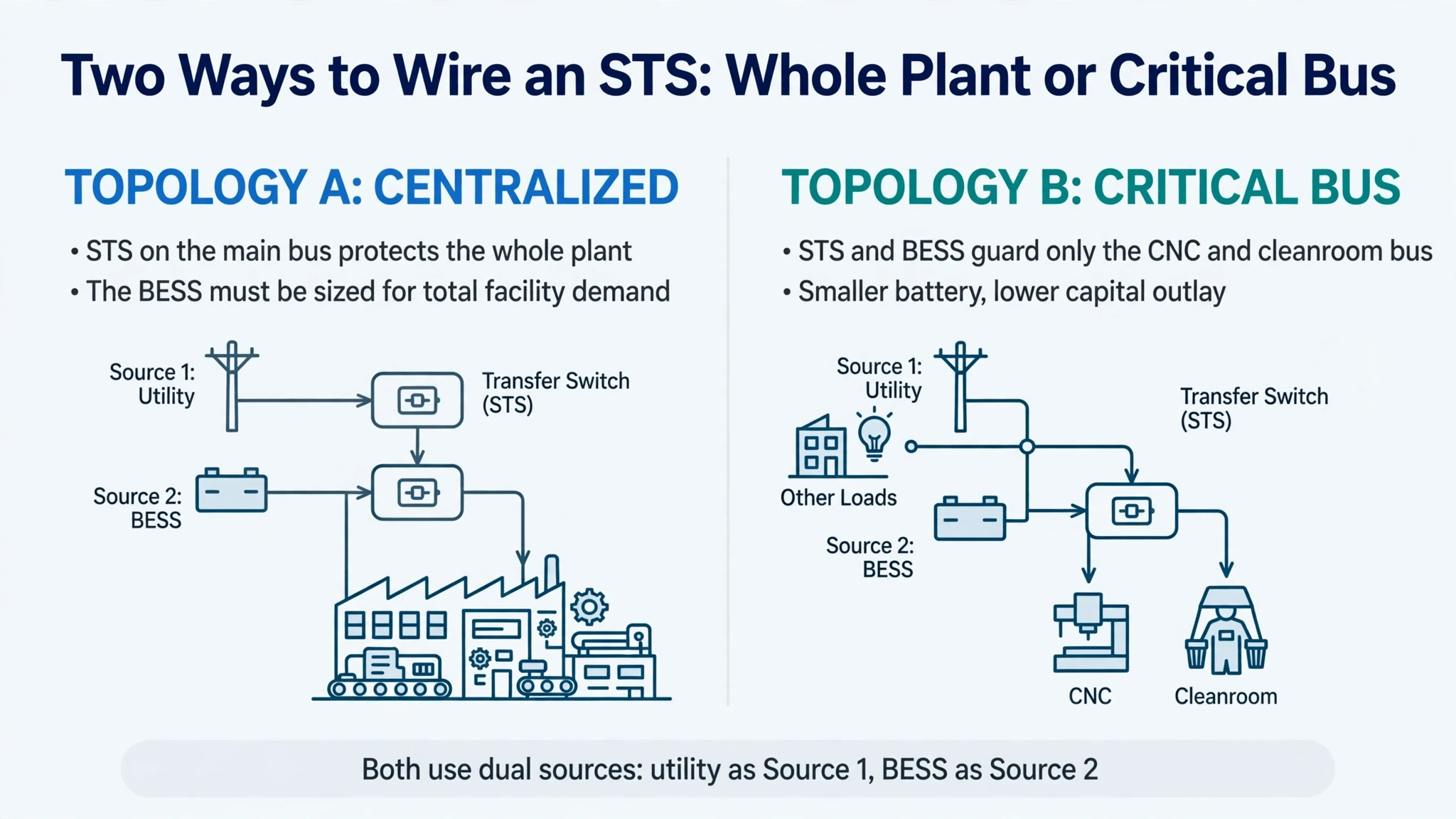
Engineering teams select between two primary electrical topologies:
- 1. Topology A (Centralized Main Low-Voltage Bus Protection):
The STS is installed directly between the utility transformer and the main plant low-voltage switchboard, with the BESS functioning as Source 2. This configuration protects the entire factory switchboard, allowing flexible load management without rewiring downstream sub-panels. Sizing requires higher PCS power capacity to carry total facility demand.
- 2. Topology B (Dedicated Critical Production Bus Protection):
The STS and BESS install ahead of a dedicated critical-load distribution board feeding high-value tools, such as five-axis machining centers or semiconductor cleanroom MCC panels. Non-critical loads (general HVAC, administrative lighting, warehouse storage) remain on the unbuffered utility line. This targeted approach lowers battery capacity requirements and optimizes capital outlay.
4.2 Handling regenerative braking energy from high-speed CNC machine tools
Modern multi-axis CNC machining centers and heavy stamping presses use variable-speed servo drives.
When a 24,000 RPM spindle decelerates rapidly, kinetic energy converts into electrical energy and flows back toward the drive DC link:
- Non-regenerative drives: If the machine drive lacks an Active Front End (AFE) or regenerative feedback unit, reverse power cannot flow back to the AC bus. In this case, energy must be dissipated locally in internal braking resistors.
- Regenerative AFE drives: When machine tools feature regenerative AFE drives or common DC bus recovery units, decelerating power flows back onto the local AC distribution panel.
- BESS energy absorption: Where regenerative power reaches the AC sub-panel, the bidirectional BESS responds quickly to absorb surplus reverse power flows, directing regenerated energy into automotive-grade LiFePO4 battery technology cells. This recovers energy that would otherwise be wasted as heat.
5. KRL Power C&I Product Matrix for Precision Manufacturing Facilities
KRL Power manufactures factory-integrated energy storage systems with dedicated power conversion and switching options tailored for industrial environments.
5.1 KRL-B100: Compact all-in-one cabinet for localized machine cells
- Rated power & capacity: 50kW / 100kWh
- Target application: Dedicated CNC cells, SMT line protection, diagnostic imaging suites, and localized testing bays
- Switching architecture: Integrated transfer system providing sub-10ms on-grid to off-grid switching
- Thermal management: Industrial HVAC cooling maintaining uniform cell temperatures
- Product reference: Review technical parameters for the KRL-B100 (50kW / 100kWh) solar-diesel BESS cabinet.
5.2 KRL-B261L: Liquid-cooled all-in-one ESS for medium manufacturing workshops
- Rated power & capacity: 125kW / 261kWh
- Target application: Cleanroom air-handling infrastructure, multi-machine precision mold shops, and optical coating facilities
- Thermal management: Closed-loop industrial liquid cooling holding cell temperature variance under 3°C, extending pack lifespan
- Enclosure rating: IP65-rated battery compartment for harsh industrial environments
- Parallel expansion: Multi-unit parallel capability up to 1MW / 2MWh
- Product reference: Inspect full electrical specifications for the KRL-B261L (125kW / 261kWh) liquid-cooled C&I ESS.
5.3 KRL-B522L & KRL-B2M6L: High-capacity systems for plant-wide facility backup
- KRL-B522L: 250kW / 522kWh integrated liquid-cooled industrial storage system with physical dimensions of 2480 × 1400 × 2050 mm, featuring 240kW MPPT with dual MPPT inputs for rooftop solar integration. Check configuration data for the KRL-B522L (250kW / 522kWh) industrial energy storage system.
- KRL-B2M6L Container Series: Standard catalog models include 750kW / 1.5MWh and 1.0MW / 2.0MWh utility-scale configurations, with project-engineered 1.2MW / 2.6MWh containerized options. Features advanced grid-forming control for large-scale industrial microgrids. Review options for the KRL-B2M6L containerized BESS series.
FAQ
What is the technical difference between an ATS and an STS in battery storage?
How does an STS-integrated BESS comply with the SEMI F47 standard?
Can an STS-integrated BESS replace both a UPS and an emergency diesel generator?
How does the system handle high motor inrush currents from CNC spindle starts?
Does a standard grid-following BESS keep CNC machines running when the utility fails?
Is a 2–4 ms STS transfer available under every source condition?
When should a plant protect only a critical bus instead of the whole factory?
What data should an EPC supply for an STS-integrated BESS sizing review?
Can a fast-switching BESS capture CNC spindle regenerative braking energy?
How should precision manufacturers compare BESS backup duration with a UPS?
6. Conclusion & Custom STS Engineering Consultation
Voltage sags and transient power disturbances represent an avoidable operational and financial risk for high-precision manufacturing facilities.
Deploying an integrated fast-switching battery storage system protects sensitive CNC machine tools, semiconductor cleanrooms, and automated assembly lines from costly downtime while generating daily revenue through energy arbitrage and demand charge management.
- For industrial facility managers and electrical directors: Contact KRL Power's engineering team to share your workshop single-line diagram (SLD), critical machine load schedule, and utility power quality history.
- For custom factory microgrids and high-inrush motor protection: Explore our OEM/ODM custom battery solutions to receive a preliminary SEMI F47 ride-through evaluation and project quotation within forty-eight hours.